hello
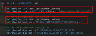
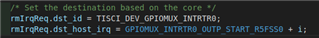
I want to know the way to configure gpio interrupts for mcu2_0 in vision_apps
I see pdk_jacinto_08_00_00_37/packages/ti/board/diag/led/src/led_test.c has a way to configure, but I don't know how to do something like this in vision_apps
Original question:

hello
I want to know the way to configure gpio interrupts for mcu2_0 in vision_apps
I see pdk_jacinto_08_00_00_37/packages/ti/board/diag/led/src/led_test.c has a way to configure, but I don't know how to do something like this in vision_apps