This thread has been locked.

If you have a related question, please click the "Ask a related question" button in the top right corner. The newly created question will be automatically linked to this question.

DM6437 VPFE interfacing with TVP5158

Other Parts Discussed in Thread: TVP5158

Hi all,

    I am using DM6437 connect with TVP5158 decoder to get 2-ch D1 image(line-interleaved mode).

1. Since the vertical blanking in the input is being masked out, we can only get the V-bit in start code(SC[0]) to indicate the end of the frame(it will cause 4 times in ), 

    is that possible we can get the VDINT interrupt signal from VPFE(to check the end of the frame by hardware, not by software)?

2. When I read the image data in beginning of the SDRAM(or in the same address), every times I will get the different line number, is that correct?

After the de-multiplexed procedure, i will get the image like this:

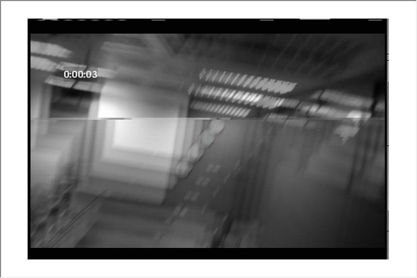
It's seem like some of the lines are copied from the next frame, is there any way to solve the problem like this?

  • Mike,


    mike ma said:

    Hi all,

        I am using DM6437 connect with TVP5158 decoder to get 2-ch D1 image(line-interleaved mode).

    1. Since the vertical blanking in the input is being masked out, we can only get the V-bit in start code(SC[0]) to indicate the end of the frame(it will cause 4 times in ),

        is that possible we can get the VDINT interrupt signal from VPFE(to check the end of the frame by hardware, not by software)?

     you can use VDINT0 and VIDINT1 of VPFE.

    mike ma said:

    2. When I read the image data in beginning of the SDRAM(or in the same address), every times I will get the different line number, is that correct?

    Can you explain(rephrase) in detail what you mean?

    And yes, looks synchronization is not handled properly, hence frame is like that.


  • Hi Nagabhushana,

        Thanks for the reply,

    1. After I tested the VPFE interrupt, I find out it will caused the interrupt about 30 times per second, but I'm not sure whether it's indicate the end of the frame,

       because I can't figure out if the vertical blanking in the input(SAV/EAV) is be masked out, what will cause the VPFE interrupt?

    2. For example, the first time input image line 1 is written to the SDRAM address 0x84000000, but in the next time, a random input image line will be written to the same  

        address 0x84000000, not the same line number, it's mean the image data sorted in SDRAM will changed and I don't know why is that happend.

  • Mike,

    VIDINT Interrupts are configured for number of lines in a frame. For each frame, after number of lines, interrupt is triggered. ISR will handle that interrupt by doing appropriate action such as scheduling next buffer. In case you have a source for the driver, you can find about this.

    Regarding SDRAM address, yes, once a frame is captured, driver programs new address in hw so that next frame is captured in different location. SDRAM addresses are programed in hw during active period because registers are shadowed. They take effect only from next v-blank.

  • Hi,Nagabhushana

    I'm faceing the same problem,how to configure the VDIN0 to reflect the end of a frame,and continue to capture next frame in another ddr2 address?

    noted that i doesn't use psp and BIOS to configure VPFE and interrupt.

    thank you.


  • my ISR doesn't work at all,with this interrupt configure:

    void SetIOInterrupt( void )
    {
     CSR=0x100;  /* disable all interrupts            */
       IER=1;   /* disable all interrupts except NMI */
       ICR=0xffff;  /* clear all pending interrupts      */  
       
     ISTP = 0x10800400;
     
       
        INTC_EVTCLR0 = 0xFFFFFFFF;
        INTC_EVTCLR1 = 0xFFFFFFFF;
        INTC_EVTCLR2 = 0xFFFFFFFF;
        INTC_EVTCLR3 = 0xFFFFFFFF;  
     

        INTC_EVTMASK3 = 0xFFFFFFFF;
        INTC_EVTMASK2 = 0xFFFFFFFE;
        INTC_EVTMASK1 = 0xFFFFFFFF;
        INTC_EVTMASK0 = 0xFEFFFFFF;//enable event 24(VDINT0)


        INTC_INTMUX2 = 0x00180000; //map to interrupt 13

        IER |= 0x00000402;//enable interrupt 13

        CSR=0x01 ;  /*enable all interrupts*/
    }

    VPFE configure:

    VPFE_CCDC_VDINT     = 0x03200000;//800 lines in a frame

    some thing wrong?

    thank you

  • Hi,


    This will be difficult to capture as CCDC works in detection mode not in configuration mode. It detects the incoming signal and captures the frame. You can capture line mued frame but driver/application will have to separate them out into independent buffers by looking into the contents of the captured frame and indentifying  line sync and frame sync bits.


    Thanks,

    Brijesh Jadav

  • what are you saiying?

    VDINT0 or VDINT1 interrupt can detect the end of frame,but in my board.this interrupt are triggerd even VPFE are not started  (VPFE_CCDC_PCR=0;)

    and now, how to configure these regs and let VDINT0 or VDINT1 to indicate frame end correctly?

    thank you.