This thread has been locked.

If you have a related question, please click the "Ask a related question" button in the top right corner. The newly created question will be automatically linked to this question.

TDA4VM: [TDA4] How to modify linux device tree for bosch SMI130 SPI interface

Part Number: TDA4VM

Dear Experts,

as title description, even modify some code, but I it still have some problems about device tree SPI attributes.

My main question is "How to set up gpio interrupt for SMI130?"

https://github.com/boschmemssolutions/SMI130-Sensor-API

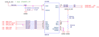
(1) Here is our schematic,

SCx --> TDA4 SPI3_CLK (Y25, PRG0_PRU1_GPO17)

SDx --> TDA4 SPI3_D1_SOUT (AA29, PRG0_PRU1_GPO19)

SDO1/SDO2 --> SPI3_D0_SIN (AA26, PRG0_PRU1_GPO18)

CSB1 --> SPI3_CS0 (AA24, PRG0_PRU1_GPO7)

CSB2 --> SPI3_CS1 (AB26, PRG0_PRU1_GPO9)

INT1 --> GYRO-INT (G25, WKUP_GPIO0_4)

INT2 --> GYRO-ACC-INT (G24, WKUP_GPIO0_5)

(2) check SPI3 in device tree is ok !

	main_spi3: spi@2130000 {
		compatible = "ti,am654-mcspi","ti,omap4-mcspi";
		reg = <0x0 0x2130000 0x0 0x400>;
		interrupts = <GIC_SPI 187 IRQ_TYPE_LEVEL_HIGH>;
		clocks = <&k3_clks 269 1>;
		power-domains = <&k3_pds 269 TI_SCI_PD_EXCLUSIVE>;
		ti,spi-num-cs = <2>;
		#address-cells = <1>;
		#size-cells = <0>;
	};

(3) check related pinmux in device tree is ok !

SPI CLK / D1_SOUT / D1_SIN /  CS0 / CS1

	main_spi3_pins_default: main_spi3_pins_default {
		pinctrl-single,pins = <
			J721E_IOPAD(0x144, PIN_OUTPUT, 4) /* (Y25) PRG0_PRU1_GPO17.SPI3_CLK */
			J721E_IOPAD(0x148, PIN_INPUT, 4) /* (AA26) PRG0_PRU1_GPO18.SPI3_D0 */
			J721E_IOPAD(0x14c, PIN_OUTPUT, 4) /* (AA29) PRG0_PRU1_GPO19.SPI3_D1 */
			J721E_IOPAD(0x11c, PIN_OUTPUT, 4) /* (AA24) PRG0_PRU1_GPO7.SPI3_CS0 */
			J721E_IOPAD(0xd4, PIN_OUTPUT, 4) /* (AB26) PRG0_PRU0_GPO9.SPI3_CS1 */
		>;
	};

two gpio interrupt define is ok ! (SMI130 gpio interrupt)

	//Gibbs@20211216
	mywkup_gpio1_pins_default: mywkup_gpio1_pins_default {
		pinctrl-single,pins = <
			J721E_WKUP_IOPAD(0xc0, PIN_INPUT, 7) /* (G25) WKUP_GPIO0_4 */
			J721E_WKUP_IOPAD(0xc4, PIN_INPUT, 7) /* (G24) WKUP_GPIO0_5 */

(4) Add SPI SMI130 node 

&main_spi3 {
    pinctrl-names = "default";
    pinctrl-0 = <&main_spi3_pins_default>;
	status="okay";

    smi130_acc@0 {
		status="okay";
		spi-max-frequency = <500000>;
		reg = <0>;
		compatible = "linux,spidev","smi130_acc";
		interrupt-parent = ??
		interrupts = ??
		smi130_acc,gpio_irq = ??
	 };
 
	 smi130_gyro@1 {
		 status="okay";
		 spi-max-frequency = <500000>;
		 reg = <1>;
		 compatible = "linux,spidev","smi130_gyro";
		 interrupt-parent = ??
		 interrupts = ??
		 smi130_gyro,gpio_irq = ??


	 };
 
};

How to stuff these attributes "interrupt-parent" "interrupt" "smi130_acc,gpio_irq" and "smi130_gyro,gpio_irq" ?

Many Thanks

Gibbs

  • Hi, 

    After few days studying, so far, my conclusion as below :

    This is sample code form bosch GitHub

      	status = "okay";
      	cs-gpios = <&msmgpio 18 0>,<&msmgpio 110 0>;
      	spi-cpol = <0>;
      	spi-cpha = <0>;
      	smi130_acc@0{
      	 			spi-max-frequency = <500000>;					
      				compatible = "smi130_acc";
      				reg = <0>;
      				interrupt-parent = <&msmgpio>;
      				interrupts = <115 0>; 
      				smi130_acc,gpio_irq = <&msmgpio 115 0>;			
      	    };
      	smi130_gyro@1{
      				spi-max-frequency = <500000>;					
      				compatible = "smi130_gyro";
      				reg = <1>;
      				interrupt-parent = <&msmgpio>;
      				interrupts = <13 0>; 
      				smi130_gyro,gpio_irq = <&msmgpio 13 0>;
      		};

    base on hardware design for TDA4,  modify device tree as below :

    * gpio interrupt input pinmux

    	mywkup_smi130_gpio_pins_default: mywkup-smi130-gpio-pins-default{
    		pinctrl-single,pins = <
    			J721E_WKUP_IOPAD(0xc0, PIN_INPUT, 7) /* (G25) WKUP_GPIO0_4 */
    			J721E_WKUP_IOPAD(0xc4, PIN_INPUT, 7) /* (G24) WKUP_GPIO0_5 */
    		>;
    	};

    *  SPI3 pinmux

    	main_spi3_pins_default: main_spi3_pins_default {
    		pinctrl-single,pins = <
    			J721E_IOPAD(0x144, PIN_OUTPUT, 4) /* (Y25) PRG0_PRU1_GPO17.SPI3_CLK */
    			J721E_IOPAD(0x148, PIN_INPUT, 4) /* (AA26) PRG0_PRU1_GPO18.SPI3_D0 */
    			J721E_IOPAD(0x14c, PIN_OUTPUT, 4) /* (AA29) PRG0_PRU1_GPO19.SPI3_D1 */
    			J721E_IOPAD(0x11c, PIN_OUTPUT, 4) /* (AA24) PRG0_PRU1_GPO7.SPI3_CS0 */
    			J721E_IOPAD(0xd4, PIN_OUTPUT, 4) /* (AB26) PRG0_PRU0_GPO9.SPI3_CS1 */
    		>;
    	};

    * Compare to Bosch GitHub sample code, I add smi130 device node under SPI3

    &main_spi3 {
       pinctrl-names = "default";
       pinctrl-0 = <&main_spi3_pins_default &mywkup_smi130_gpio_pins_default>;
       status="okay";

       smi130_acc@0 {
       status="okay";
       spi-max-frequency = <500000>;
       reg = <0>;

       compatible = "smi130_acc";
       interrupt-parent = <&wkup_gpio0>;
       interrupts = <?? IRQ_TYPE_LEVEL_HIGH>;  
       smi130_acc,gpio_irq = <&wkup_gpio0 ?? IRQ_TYPE_LEVEL_HIGH>;
       #address-cells = <2>;

      };

       smi130_gyro@1 {
       status="okay";
       spi-max-frequency = <500000>;
       reg = <1>;
       compatible = "smi130_gyro";
       interrupt-parent = <&wkup_gpio0>;
       interrupts = <?? IRQ_TYPE_LEVEL_HIGH>; 
       smi130_gyro,gpio_irq = <&wkup_gpio0 ?? IRQ_TYPE_LEVEL_HIGH>;
       #address-cells = <2>;
       };

    };

    1. Is this correct device tree stuff for SMI130?

    2. How do I fill in the interrupt number ?? (as question mark ??)

    Thanks very much for your comment.

    Gibbs

  • Hi GIbbs,

    There is app note that you can refer for SPI validation. Please look at the pinmux changes: https://www.ti.com/lit/pdf/sprad26?keyMatch=DRA821

    2. How do I fill in the interrupt number ?? (as question mark ??)

    It should be the number of GPIO in the wkup GPIO domain. As per your DT description it should be 4 & 5?

    - Keerthy