This thread has been locked.

If you have a related question, please click the "Ask a related question" button in the top right corner. The newly created question will be automatically linked to this question.

TMS320C6474: Mezzanine EVM Board embedded emulator circuit

Part Number: TMS320C6474
Other Parts Discussed in Thread: SN74AUC1G19

Hello,

Our company is still using "TMS320C6474 Mezzanine EVM Board" and recently Spectrum Digital stopped manufacturing these boards.

We managed to acquire the PCB layout, schematics and BOM for this specific card as an option in case we want to manufacture them.

The drill that those resources are missing the embedded emulator circuit, the BOM and schematics dont include any thing related to  the embedded emulator circuit.
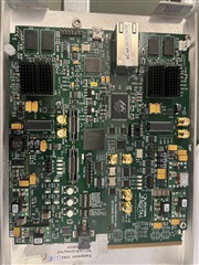
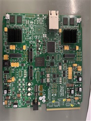
Original Card with embedded emulator

Card with embedded emulator

Card without embedded emulator

Card without the embedded emulator

Now according to JTAG TOPOLOGY there some kind of detection of which kind of JTag connection is being used. 
My question is: is it possible to connect via JTag 60PIN to DSP using XDS 560 v2 Emulator without the existence of  the embedded emulator Circuit?

if no, can you specify the reason?

if yes, how? (hints are welcome)

Thanks,

Boutros Farah 

  • Hello Boutros,

    I don't have any experience with this specific board but from looking a technical manual and your description I don't believe you can connect to the device with a 60-Pin connector because from what I can tell, the 60-Pin connector was going through the embedded emulator circuit and into the hardware so without that you would not be able to talk to the DSP with the XDS 560. I think your only option would be to use the 14 pin JTAG instead.

    Best Regards,

    Ralph Jacobi

  • Hello Ralph,

    thanks for your reply, the thing is the 14 PINS JTAG connector also go through the embedded emulator circuit, what the difference between it and the 60 PIN?

    Thanks,

    Boutros Farah

  • Hi Boutros,

    I went back to look through the schematic again and I seem to have misinterpreted it.

    So there are a few elements on this board:

    1. JTAG Emulator Circuit
    2. 14 Pin JTAG interface
    3. 60 pin TI JTAG header #1
    4. 60 pin TI JTAG header #2

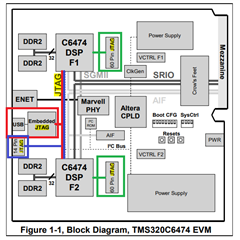
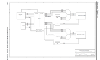
    The block diagram shows the following:

    I color colored this very intentionally to also highlight how these elements are described in the document:

    The EVM incorporates Spectrum Digital’s embedded JTAG emulation, a 14 pin JTAG interface and 2 - 60 pin TI JTAG/Trace headers. A CPLD is used for routing the various JTAG paths so that no user switches or hardware configuration is required. The board supports both C6474 devices in the JTAG scan chain when used with the on-board emulation or 14 pin JTAG header J10. When the 60 pin JTAG header is used only one C6474 device is connected to that header. There is a 60 pin JTAG header for each cpu. If only one 60 pin JTAG header is used, the other C6474 device is accessible via its 14 pin or 60 pin JTAG emulation connector.

    So basically how this board is setup is that you have multiple options:

    1) Use the USB connector to access embedded JTAG emulator and debug BOTH C6474 devices

    2) Use 14-pin JTAG connector to debug BOTH C6474 devices

    3) Use a 60-pin JTAG connect to debug ONE specific C6474 device - the other can be accessed via 14-pin or Embedded JTAG

    4) Use 2x 60-pin JTAG and you can debug BOTH C6474 without the 14-pin or Embedded JTAG 

    The block diagram lends to that with how it shows the routing paths where the 60 pin connectors go straight to the C6474 DSP.

    So based on that, I reviewed the schematic again and I see dedicated pages for the 60-pin JTAG headers connecting to the C6474 DSP and I don't see anything there which makes me think it is dependent on the Embedded JTAG.

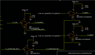
    The Embedded JTAG page doesn't indicate it does anything but detect and use a buffer to pass through the right signals.

    So there is only one piece I don't really know about which is what would happen if that buffer is there without the Embedded JTAG Emulator.

    There are two possibilities I see:

    1. The 60 pin connector will work fine on the board without the embedded JTAG emulator in place
    2. The buffer between the JTAG signals that is part of selecting which device gets to program the C6476 DSP is blocking the 60-pin header signals because the embedded JTAG emulator is missing and can't control the buffer to pass the signals through.

    If happens, which honestly, that'd be my hunch... then the solution is to remove the buffers which are unnecessary and route the JTAG signals directly to the C6474 devices.

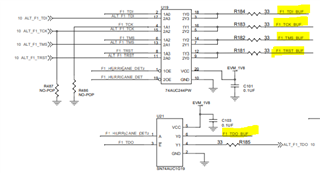
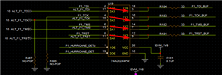
    It looks like the buffers are across two devices per 60-pin connector:

    1. 74AUC244PW (U19, U32)
    2. SN74AUC1G19 (U21, U34)

    The signals making it to the C6474 seem to be the BUF ones I highlighted:

    I think that should give you enough information to run with from here - thanks for the follow-up, it was a great question because it helped me re-consider what I had first seen and that lead me down this rabbit hole. Originally I saw how the buffered connections were setup and assumed the Embedded JTAG was managing the 60 pin headers - but in reality it just controlled the buffers for a few signals and that provides the option to work around the lack of that element as I've highlighted.Slight smile

    Best Regards,

    Ralph Jacobi

  • Hello Ralph,

    Thank you again for your in-depth suggestion.

    Today, I took your advice and bypassed the buffer U19 (I dissembled it) and shorted the inputs of each signal to the output directly (2->3 | 4->5 | 6-7 | 8-> 9)

    I also dissembled U21 and shorted pin 3 to pin 6

    Reattempting to connect to DSP with these modifications resulted in the same output as before

    [Start: Blackhawk XDS560v2-USB System Trace Emulator]
    
    Execute the command:
    
    %ccs_base%/common/uscif/dbgjtag.exe -f %boarddatafile% -rv -o -F inform,logfile=yes -S pathlength -S integrity
    
    [Result]
    
    
    -----[Print the board config pathname(s)]------------------------------------
    
    C:\Users\ENG~1.ADM\AppData\Local\TEXASI~1\
        CCS\ccs1040\0\0\BrdDat\testBoard.dat
    
    -----[Print the reset-command software log-file]-----------------------------
    
    This utility has selected a 560/2xx-class product.
    This utility will load the program 'bh560v2u.out'.
    Loaded FPGA Image: C:\ti\ccs1040\ccs\ccs_base\common\uscif\dtc_top.jbc
    The library build date was 'Jun 25 2021'.
    The library build time was '16:06:55'.
    The library package version is '9.4.0.00129'.
    The library component version is '35.35.0.0'.
    The controller does not use a programmable FPGA.
    The controller has a version number of '6' (0x00000006).
    The controller has an insertion length of '0' (0x00000000).
    The cable+pod has a version number of '8' (0x00000008).
    The cable+pod has a capability number of '7423' (0x00001cff).
    This utility will attempt to reset the controller.
    This utility has successfully reset the controller.
    
    -----[Print the reset-command hardware log-file]-----------------------------
    
    The scan-path will be reset by toggling the JTAG TRST signal.
    The controller is the Nano-TBC VHDL.
    The link is a 560-class second-generation-560 cable.
    The software is configured for Nano-TBC VHDL features.
    The controller will be software reset via its registers.
    The controller has a logic ONE on its EMU[0] input pin.
    The controller has a logic ONE on its EMU[1] input pin.
    The controller will use falling-edge timing on output pins.
    The controller cannot control the timing on input pins.
    The scan-path link-delay has been set to exactly '2' (0x0002).
    The utility logic has not previously detected a power-loss.
    The utility logic is not currently detecting a power-loss.
    Loaded FPGA Image: C:\ti\ccs1040\ccs\ccs_base\common\uscif\dtc_top.jbc
    
    An error occurred while hard opening the controller.
    
    -----[An error has occurred and this utility has aborted]--------------------
    
    This error is generated by TI's USCIF driver or utilities.
    
    The value is '-233' (0xffffff17).
    The title is 'SC_ERR_PATH_BROKEN'.
    
    The explanation is:
    The JTAG IR and DR scan-paths cannot circulate bits, they may be broken.
    An attempt to scan the JTAG scan-path has failed.
    The target's JTAG scan-path appears to be broken
    with a stuck-at-ones or stuck-at-zero fault.
    
    [End: Blackhawk XDS560v2-USB System Trace Emulator]
    

    What bothers me there still Signals EMU 0 and EMU 1, according yo your expertise, any idea if they play role in DSP detection or not?

    Best Regards,

    Boutros Farah

  • Hi Boutros,

    Unfortunately my full expertise is with lower end MCUs - because I work with LaunchPad & JTAG in general, I was able to make some educated guesses regarding the JTAG lines and how a USB emulator would be used (we use these in LaunchPads all the time). But I am not familiar with higher end Debug probes and how EMU0 or EMU 1 is used.

    You might be able to make a probe specific E2E question so the tools team could comment if the error you got is related to EMU0/EMU1 not being connected.

    Also I am not sure how the whole circuit is built out but usually there are pull-up / pull-down resistors on JTAG lines so you may need to verify those are still present.

    Best Regards,

    Ralph Jacobi