This thread has been locked.

If you have a related question, please click the "Ask a related question" button in the top right corner. The newly created question will be automatically linked to this question.

TDA4VM: DCC LDC Tuning: Configure optical centre

Part Number: TDA4VM

Hi 

This is with regard to tuning LDC node with DCC. 

Is there any way to configure optical center such that distortion can be corrected around the optical center as we do it for LSC in DCC. 

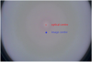
We need this because the center of the lens does not match the image center as shown in the shading profile below and this adds to the distortion after LGD correction. It would be helpful the mesh can be configured in a way to match the optical center. 

Any help with regards to this is highly appreciated.

Thanks, 

Apeksha Chipade

  • Hi Gang

    Thank you for your response. 

    With the change in optical center, mustache distortion is reduced but perspective distortion is introduced because of mesh center offset. 
    Is there a way to correct perspective distortion? Could you please provide a guide on tuning affine transform coefficients?

    Kindly see the reference image that has perspective distortion introduced. 

    Best regards, 

    Apeksha Chipade

  • Hi Apeksha,

    You may add the perspective change into your mesh LUT as well or use the perspective transform if the change is very small.

    Best,
    Gang

  • Hi Gang, 

    Thank you for your response.

    We applied perspective transform to the image and can see that the perspective distortion is eliminated. 

    The same is applied to the mesh grid as below for mesh generation  

        pts1 = np.float32([[335, 129], [2193, 121],
                            [165, 1300], [2360, 1300]])
        pts2 = np.float32([[165, 130], [2360, 130],
                            [165, 1300], [2360, 1300]])
        pts1 = pts1 / (pow(2,m))
        pts2 = pts2 / (pow(2,m))
           
        matrix = cv2.getPerspectiveTransform(pts1, pts2)
        mh = cv2.warpPerspective(mh, matrix, mh.shape)
        mv = cv2.warpPerspective(mv, matrix, mv.shape)
    We get the following error on running the LDC simulation in DCC when the mesh with perspective transform correction is loaded: 
    Function process exited with error code: 4 - CANNOT_OPEN_INFILE
    Plugin returned message:

    LDC return error code: 5
    Simulator failed!


    LDC error flags:
    bit0 = 1: out of input image frame bound or mesh frame bound (warning only: clipped back)
    bit1 = 0: out of pixel block bound (PIXPAD is too small; warning only: clipped back)
    bit2 = 1: internal pixel buffer overflow (input image block is too big)
    bit3 = 0: internal mesh buffer overflow (mesh down sampling is too small)
    bit4 = 0: affine/pwarp internal overflow
    bit5 = 0: out of mesh block bound (warning only: clipped back)
    The mesh generated with and without the perspective transform correction has the same size
    Also, DCC does not generate any errors for generating simulated output with the mesh without perspective transform. 
    Kindly let us know if there is any other way to correct the perspective transform. 
    Thank you. 
    Best regards, 
    Apeksha Chipade
  • You may try the semi-auto mode or reduce the output block size manually.

  • Hi Gang, 

    Thank you for your inputs, yes, we tried reducing the output block size, but the simulated output is not as expected. 

    It appears the perspective transform applied to the mesh LUT is not getting applied properly. 

    Kindly let us know how to apply perspective transform to the mesh LUT generated. 

    Thank you. 

    Best regards, 

    Apeksha Chipade

  • Hi Apeksha,

    OK, you mean the new LUT does not give you the correct transform.

    The same is applied to the mesh grid as below for mesh generation  

    This shall be fine if everything is done correctly.
    For example, if you need all your output image pixels to move to the right for 10 pixels, the H coordinates (for input pixels) shall be subtracted by 10 pixels.
    You will also need to use the correct integer encoding format for "mh, mv" pairs (they are differences and encoded in in an integer format).
    The FAQ has the information in matlab/octave code.

    You may implement a simple 10-pixel right-shift and a simple 10-degree clock-wise rotation first.
    Once you get both of those correct, you shall have the correct flow for inserting your warp.

    Best,
    Gang