Hi Champs
Could you give me a tuning guide regarding CAMERA VPFE?
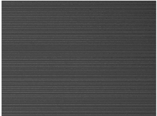
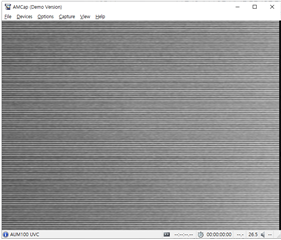
The customer found a step phenomenon of the captured image on AM4372, and is looking for a related method. Please give us your opinion on whether we can handle it on VPFE.
The engineer of the customer thinks that the VPFE driver of the EVM has strong sharpness in the default setting, so please review if there is a way to change various settings.
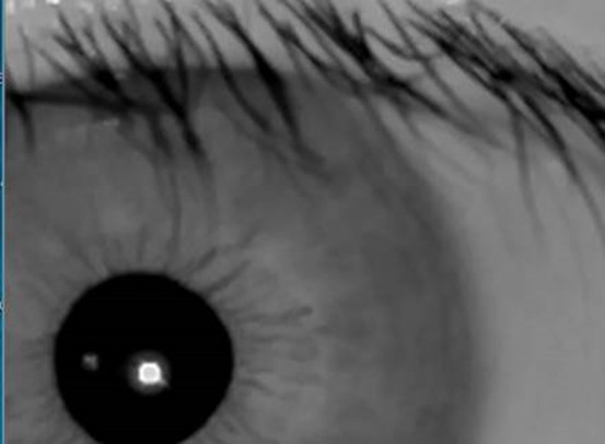
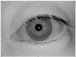
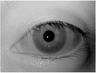
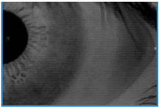
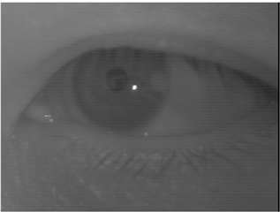
The figure of bottom left (figure 1) is captued from AM4372 EVM, But The image of bottom right (figure 2) is their expected result.
Thank you.
Regards,
Jack
Figure 1.
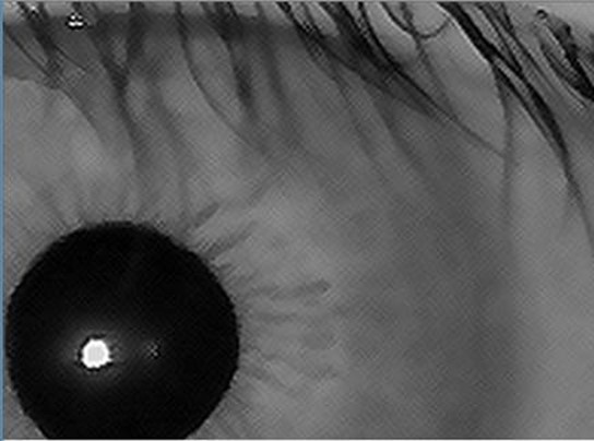
Figure 2.