Other Parts Discussed in Thread: SYSCONFIG
Hello,
I'm currently working on the TMDS64GPEVM board and i'm trying to use the example : "gpio_input_interrupt_am64x-evm_r5fss0-0_nortos_ti-arm-clang" implementation into another example : "empty_am64x-evm_system_freertos".
I modified the "empty_am64x-evm_system_freertos" exemple to only work with R5FSS0_0 and R5FSS0_1.
I modified the empty tasks of the example to not exit immediately (add while(1) loop before calling board_drivers_close and drivers_close).
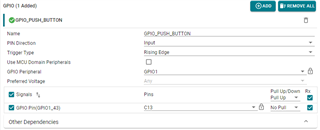
I configured the sysconfig to have the GPIO1_43 input with rising edge trig type on the R5FSS0_1 core INSTEAD of the R5FSS0_1 core.
I copied the interrupt initialization from the "gpio_input_interrupt_am64x-evm_r5fss0-0_nortos_ti-arm-clang" example, changing only the core number:
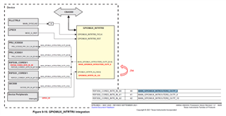
CSLR_R5FSS0_CORE1_INTR_MAIN_GPIOMUX_INTROUTER0_OUTP_8
Instead of
CSLR_R5FSS0_CORE0_INTR_MAIN_GPIOMUX_INTROUTER0_OUTP_8.
I see that a call to sciclient is done in the "gpio_input_interrupt_am64x-evm_r5fss0-0_nortos_ti-arm-clang" example. Do I have to use this init too?
Both cases (sciclient init or not) the interrupt is never triggered.
I don't fully understand how to initialize a simple GPIO interrupt, do you have some information for me?
Why using the INTROUTER0_OUTP_8 and not the INTROUTER0_OUTP_0 for example?
I go step by step and the next modification is to change GPIO1_43 input with another one (MCU_GPIO0_7 for example)
Here is my code:
/*
* Copyright (C) 2021 Texas Instruments Incorporated
*
* Redistribution and use in source and binary forms, with or without
* modification, are permitted provided that the following conditions
* are met:
*
* Redistributions of source code must retain the above copyright
* notice, this list of conditions and the following disclaimer.
*
* Redistributions in binary form must reproduce the above copyright
* notice, this list of conditions and the following disclaimer in the
* documentation and/or other materials provided with the
* distribution.
*
* Neither the name of Texas Instruments Incorporated nor the names of
* its contributors may be used to endorse or promote products derived
* from this software without specific prior written permission.
*
* THIS SOFTWARE IS PROVIDED BY THE COPYRIGHT HOLDERS AND CONTRIBUTORS
* "AS IS" AND ANY EXPRESS OR IMPLIED WARRANTIES, INCLUDING, BUT NOT
* LIMITED TO, THE IMPLIED WARRANTIES OF MERCHANTABILITY AND FITNESS FOR
* A PARTICULAR PURPOSE ARE DISCLAIMED. IN NO EVENT SHALL THE COPYRIGHT
* OWNER OR CONTRIBUTORS BE LIABLE FOR ANY DIRECT, INDIRECT, INCIDENTAL,
* SPECIAL, EXEMPLARY, OR CONSEQUENTIAL DAMAGES (INCLUDING, BUT NOT
* LIMITED TO, PROCUREMENT OF SUBSTITUTE GOODS OR SERVICES; LOSS OF USE,
* DATA, OR PROFITS; OR BUSINESS INTERRUPTION) HOWEVER CAUSED AND ON ANY
* THEORY OF LIABILITY, WHETHER IN CONTRACT, STRICT LIABILITY, OR TORT
* (INCLUDING NEGLIGENCE OR OTHERWISE) ARISING IN ANY WAY OUT OF THE USE
* OF THIS SOFTWARE, EVEN IF ADVISED OF THE POSSIBILITY OF SUCH DAMAGE.
*/
#include <stdio.h>
#include <kernel/dpl/DebugP.h>
#include <kernel/dpl/AddrTranslateP.h>
#include <kernel/dpl/HwiP.h>
#include "ti_drivers_config.h"
#include "ti_drivers_open_close.h"
#include "ti_board_open_close.h"
#include <drivers/gpio.h>
#include <board/led.h>
#define OUTPUT_PIN_0 5
#if 1
#define INPUT_PIN_0 43
#endif
#if 0
#define INPUT_PIN_1 7
#endif
#if 1
static uint32_t gGpioBaseAddr;
static HwiP_Object gGpioHwiObject;
#endif
#if 0
static uint32_t gMcuGpioBaseAddr;
static HwiP_Object gMcuGpioHwiObject;
#endif
#if 1
static uint8_t gToggle = 0;
#endif
extern LED_Handle gLedHandle[CONFIG_LED_NUM_INSTANCES];
/*
* This is an empty project provided for all cores present in the device.
* User can use this project to start their application by adding more SysConfig modules.
*
* This application does driver and board init and just prints the pass string on the console.
* In case of the main core, the print is redirected to the UART console.
* For all other cores, CCS prints are used.
*/
#if 1
static void GPIO_pinIsrFxn(void *args)
{
/*
* Handle pin interrupt - This is pulse interrupt. No need to clear status
*/
if (gToggle != 1)
{
LED_on(gLedHandle[CONFIG_LED0], 0);
gToggle = 1;
}
else
{
LED_off(gLedHandle[CONFIG_LED0], 0);
gToggle = 0;
}
}
#endif
#if 0
static void MCU_GPIO_pinIsrFxn(void *args)
{
/*
* Handle pin interrupt - This is pulse interrupt. No need to clear status
*/
if (gToggle != 1)
{
LED_on(gLedHandle[CONFIG_LED0], 0);
gToggle = 1;
}
else
{
LED_off(gLedHandle[CONFIG_LED0], 0);
gToggle = 0;
}
}
#endif
void empty_main(void *args)
{
/* Open drivers to open the UART driver for console */
Drivers_open();
Board_driversOpen();
LED_on(gLedHandle[CONFIG_LED0], 0);
//BO_220628
#if 1
//GPIO1_43 is connected to button on EVM
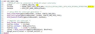
uint32_t pinNum = INPUT_PIN_0;
uint32_t intrNum = CSLR_R5FSS0_CORE1_INTR_MAIN_GPIOMUX_INTROUTER0_OUTP_8; // Why 8?
uint32_t bankNum = GPIO_GET_BANK_INDEX(pinNum);
/* Address translate */
gGpioBaseAddr = (uint32_t) AddrTranslateP_getLocalAddr(CSL_GPIO1_BASE);
/* Setup GPIO for interrupt generation */
GPIO_setDirMode(gGpioBaseAddr, pinNum, GPIO_DIRECTION_INPUT);
GPIO_setTrigType(gGpioBaseAddr, pinNum, GPIO_TRIG_TYPE_RISE_EDGE);
GPIO_bankIntrEnable(gGpioBaseAddr, bankNum);
/* Register pin interrupt */
HwiP_Params hwiPrms;
HwiP_Params_init(&hwiPrms);
hwiPrms.intNum = intrNum;
hwiPrms.callback = &GPIO_pinIsrFxn;
hwiPrms.args = (void *) pinNum;
int32_t retVal = HwiP_construct(&gGpioHwiObject, &hwiPrms);
DebugP_assert(retVal == SystemP_SUCCESS );
#endif
#if 0
//MCU_GPIO0_7 will be connected to MCU_GPIO0_8 output externally
pinNum = INPUT_PIN_1;
intrNum = CSLR_R5FSS0_CORE1_INTR_MCU_MCU_GPIOMUX_INTROUTER0_OUTP_0; // Why 0?
bankNum = GPIO_GET_BANK_INDEX(pinNum);
/* Address translate */
gMcuGpioBaseAddr = (uint32_t) AddrTranslateP_getLocalAddr(CSL_MCU_GPIO0_BASE);
/* Setup GPIO for interrupt generation */
GPIO_setDirMode(gMcuGpioBaseAddr, pinNum, GPIO_DIRECTION_INPUT);
GPIO_setTrigType(gMcuGpioBaseAddr, pinNum, GPIO_TRIG_TYPE_RISE_EDGE);
GPIO_bankIntrEnable(gMcuGpioBaseAddr, bankNum);
/* Register pin interrupt */
HwiP_Params_init(&hwiPrms);
hwiPrms.intNum = intrNum;
hwiPrms.callback = &MCU_GPIO_pinIsrFxn;
hwiPrms.args = (void *) pinNum;
retVal = HwiP_construct(&gMcuGpioHwiObject, &hwiPrms);
DebugP_assert(retVal == SystemP_SUCCESS );
#endif
//END_BO_220628
DebugP_log("R5FSS0-1 : All tests have passed!!\r\n");
/*
static uint8_t prev;
uint8_t curr;
*/
while (1)
{
/*
curr = GPIO_pinRead(gGpioBaseAddr, INPUT_PIN_0);
//Detect rising edge
if (curr == 1 && prev == 0)
{
LED_on(gLedHandle[CONFIG_LED0], 0);
}
//Detect falling edge
if (curr == 0 && prev == 1)
{
LED_off(gLedHandle[CONFIG_LED0], 0);
}
prev = curr;
*/
}
Board_driversClose();
Drivers_close();
}
Sincerely,
Bastien