This thread has been locked.

If you have a related question, please click the "Ask a related question" button in the top right corner. The newly created question will be automatically linked to this question.

66AK2G12: Debugging custom board of 66ak2g12 issue

Part Number: 66AK2G12
Other Parts Discussed in Thread: TPS65911

Hi,

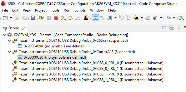
We have designed our custom board of 66ak2g12 EVM. We were trying to debug using XDS110 DEBUG PROBE but the target is not able connect and we are getting error on test connection.

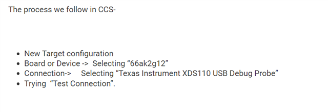
The process we follow in CCS-


  • New Target configuration
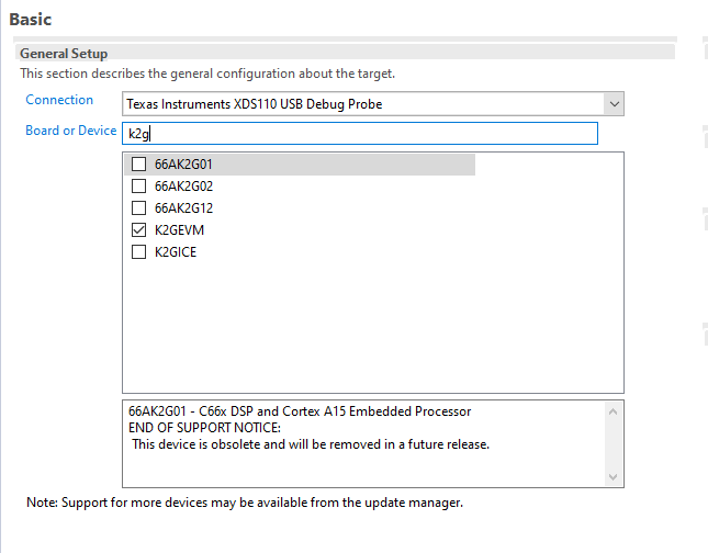
  • Board or Device ->  Selecting “66ak2g12”
  • Connection->     Selecting “Texas Instrument XDS110 USB Debug Probe”
  • Trying  “Test Connection”.


But it throws an error and not successfully connecting to board. The error log I’m attaching as a text file.


Please guide us to resolve the issue.

Thanks & Regards

Asif

[Start: Texas Instruments XDS110 USB Debug Probe_0]

Execute the command:

%ccs_base%/common/uscif/dbgjtag -f %boarddatafile% -rv -o -S integrity

[Result]


-----[Print the board config pathname(s)]------------------------------------

C:\Users\ASIF~1.MAL\AppData\Local\TEXASI~1\
    CCS\ccs1020\0\0\BrdDat\testBoard.dat

-----[Print the reset-command software log-file]-----------------------------

This utility has selected a 100- or 510-class product.
This utility will load the adapter 'jioxds110.dll'.
The library build date was 'Jan  1 2021'.
The library build time was '11:25:57'.
The library package version is '9.3.0.00032'.
The library component version is '35.35.0.0'.
The controller does not use a programmable FPGA.
The controller has a version number of '5' (0x00000005).
The controller has an insertion length of '0' (0x00000000).
This utility will attempt to reset the controller.
This utility has successfully reset the controller.

-----[Print the reset-command hardware log-file]-----------------------------

The scan-path will be reset by toggling the JTAG TRST signal.
The controller is the XDS110 with USB interface.
The link from controller to target is direct (without cable).
The software is configured for XDS110 features.
The controller cannot monitor the value on the EMU[0] pin.
The controller cannot monitor the value on the EMU[1] pin.
The controller cannot control the timing on output pins.
The controller cannot control the timing on input pins.
The scan-path link-delay has been set to exactly '0' (0x0000).

-----[An error has occurred and this utility has aborted]--------------------

This error is generated by TI's USCIF driver or utilities.

The value is '-233' (0xffffff17).
The title is 'SC_ERR_PATH_BROKEN'.

The explanation is:
The JTAG IR and DR scan-paths cannot circulate bits, they may be broken.
An attempt to scan the JTAG scan-path has failed.
The target's JTAG scan-path appears to be broken
with a stuck-at-ones or stuck-at-zero fault.

[End: Texas Instruments XDS110 USB Debug Probe_0]

  • Hello Asif,

    Were you able to connect to TI's K2G EVM?

    Regards,

    Jianzhong

  • Hi Jianzhong,

    Yes we are able to connect Ti's K2G EVM.

    Regards

    Asif

  • Hi Asif,

    Let me loop in our HW debug expert.

    Regards,

    Jianzhong

  • What are the differences between your JTAG connections relative to the JTAG connections on the TI K2G EVM?

    Regards,
    Paul

  • Hi Peaves,

    i'm attaching the JTAG schematics that we are using. On EVM  onboard debugger is there, we are using that.

    The reference for the schematic  is taken from EVM schematic itself.

    Regards

    Asif

  • If you installed RU13 and RU5 at the same time the two resistors would create a voltage divider that produces a 1V output. This causes the EMU1 voltage to be in the undefined region for CMOS input and very likely to be considered a low input. Both EMU0 and EMU1 pins need to be high for normal operation. 

    Some debuggers may consume power from pin 3 on the 14-pin JTAG connector to operate level-shifters inserted in the signal path. If so, the debugger may not expect a 500 ohm series resistor in this path.

    Remove RU13 first and see if that resolves your issue. If not, also try replacing RU6 with a 0 ohm resistor.

    Regards,
    Paul

  • I edited my previous reply to clarify what you should try.

    Regards,
    Paul

  • Dear paul,

                     thanks for the support. we have tried the below configurations but still test connection is failing. check once.

                               1. RU7, RU8, RU9, RU10 resistors shorted : RU12,RU13 opened : RU11 TRST pin Pull down (4.7k) : RU1, RU2, RU3, RU4, RU5 and added Pull-up resistor to EMUO0 (4.7k).

                                2. Removed all the Pull-up resistors (RU1, RU2, RU3, RU4, RU5), Shorted RU7, RU8,RU9, RU10, opened RU12, RU13.

    Regards,

    Asif.

  • I didn't notice that you had not included a pull-up on EMU0.

    The configuration described in option 1 should be okay.  Are you sure all power supplies, resets, and clocks are being provided to the device?

  • hi,

         we have checked the power supplies, PORn pins.  Power supply to 66AK2G12 is applied from PMIC TPS65911. they are fine. attached image for reference. During connection with debugger, captured the image by connecting TMS, TCK, TDI and TDO in oscilloscope. please check and suggest us.

    Regards

    Asif

  • I am not able to see any toggle on TMS or TDI which is required for the debugger to connect with the device.

    I can only assume you have a configuration issue with you debugger software.

    I'm going to assign this thread to the CCS team to see if they have any suggestions.

    Regards,
    Paul

  • Hi Paul,

    I have mentioned the process of configuration at the beginning of the thread, also which debugger we are using. Please let us know is there any additional step is required or any mistake we are doing in the process.

    I'm attaching  the snap of the process of configuration.

    Note: After following this process we are getting some error  that I have attached at the beginning of the thread.

    Regards

    Asif

  • Asif,

    Just to step back a bit.  As I am a bit confused on what works and what does not.

    You mentioned "On EVM  onboard debugger is there, we are using that."

    The TI EVM I believe has an on-board XDS200 class debug probe.  If you connect your XDS110 to the JTAG header on the TI EVM does that work fine?  That might be a bit tricky as I believe the EVM only has a 60pin MIPI header so an adapter would be needed to connect to it.

    TI EVM using onboard XDS200 = WORKS

    TI EVM using external XDS110 = ?

    Custom board using external XDS110 = NOT WORKING

    I can see if we have the TI EVM and adapter here to try as well.

    Regards,

    John

  • I had a colleague try the similar K2H EVM with an external XDS110 connected to the MIPI60 header with adapters.  That worked fine.

    Regards,

    John

  • Hi John, 

    We are facing the same issue while connecting EVM with an external debugger (XDS110/XDS200).

    Regards

    Asif

  • It is not clear how TI can help you solve a problem, which appears to be something related to your board.

    You need to understand why the TMS and TDI signals from the debugger are not toggling when it tries to connect.

    Regards,
    Paul

  • Hi Paul,

    We are facing the same issue while connecting external XDS110/XDS200 with EVM. It seems like there's no issue with our board.

    Thanks

    Asif

  • I do not know how I can help you with this issue. I do not have any experience using CCS or debuggers. I can only help if you have an issue with voltage levels of signals or issues with timing relationship of signals.

    I will re-assign this thread back to the CCS team since you never answered John's question "TI EVM using external XDS110 = ?".

    Maybe they can review your CCS configuration vs their CCS configurations when successfully connecting to the EVM.

    Regards,
    Paul

  • Hi John,

    TI EVM using external XDS110 = Not working (Facing same issue).

    Regards

    Asif

  • I was able to connect to my K2G EVM using an external XDS110 debug probe when using J19 on the EVM:

    My config:

    I can connect to both DSP and ARM without issue:

    Note that when I try using the JTAG header on J7, while the connectivity test passes I get connection errors when trying to connect to either core with CCS. I'm not sure what is the reason for this. I recommend using J19 for now.

    Thanks

    ki