Hi TI,
We implement the sending and receiving functions of CANFD.
However, when sending and receiving at the same time through the CAN bus,
he details are as follows:
SDK Version:8.0.
CAN bus status:
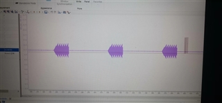
1)Introduction to sending messages:2 frames of 10ms periodic message、9 frames of 20ms periodic message、5 frames of 100ms periodic message
2)Introduction to receiving messages:8 frames of 50ms periodic message
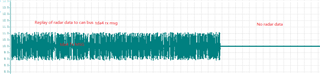
When abnormal,The 100ms periodic message cannot be sent because the CAN core is in the receiving state, that is:
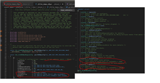
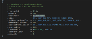
1. We use MCAN_MEM_TYPE_BUF mode to send can msg
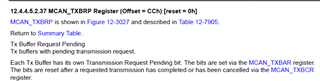
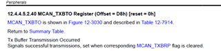
2.MCAN_TXBTO.TO0 is always zero , when MCAN_TXBRP.TRP0 register is from 1 to 0
3.In this status MCAN_PSR register BO=0,and ACT=2
So What could be the cause of this problem? how to solve?
ref: