This thread has been locked.

If you have a related question, please click the "Ask a related question" button in the top right corner. The newly created question will be automatically linked to this question.

Why so big difference between S-video input and compositve input on EVM6437

Other Parts Discussed in Thread: TVP5146

Dear Sir :

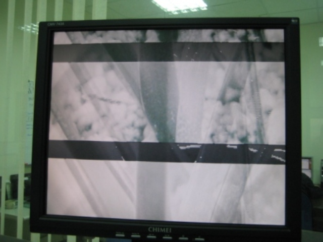
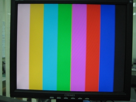
I am new to EVM6437, I use the sample code(lookback) provided from 3th party, why we can see the output normally when using s-video channel, but output abnormal when using compositive channel. We check the initialization on VPFE and VPBE and found nothing strange, besides, trace the memory on CCDC->SDR_ADDR, we found the data does not change and keep 0x10801080 even though we play a picture from the TV-OUT and feed into the AV-IN on EVM6437.

below is the code :

======================================================

#define NTSC            1
#define PAL             0

#define COLORBARS       1
#define LOOPBACK        0

#define SVIDEO_OUT      1
#define COMPOSITE_OUT   0

Uint32 vpfe_addr=0x84000000;
Uint32 vpbe_addr=0x86000000;

/* ------------------------------------------------------------------------ *
 *                                                                          *
 *  vpfe_init( ntsc/pal )                                                   *
 *                                                                          *
 * ------------------------------------------------------------------------ */
static void vpfe_init( Uint32 ntsc_pal_mode )
{
    Uint32 video_buffer = vpfe_addr;//VPFE_DDR2_ADDR;//DDR_BASE + ( DDR_SIZE / 2 );
    Uint32 width;
    Uint32 height;

    if ( ntsc_pal_mode == NTSC )
    {
        width   = 720;
        height  = 480;
    }
    else
    {
        width   = 720;
        height  = 480;
    }


    VPFE_CCDC_SYN_MODE  = 0x00032F84; // interlaced, with VD pority as negative
    VPFE_CCDC_HD_VD_WID = 0x00000000; // H-sync pulse width=0; V-sync width=0;
    VPFE_CCDC_PIX_LINES = 0;

    /*
     *  sph = 1, nph = 1440, according to page 32-33 of the CCDC spec
     *  for BT.656 mode, this setting captures only the 720x480 of the
     *  active NTSV video window
     */
    VPFE_CCDC_HORZ_INFO = width << 1;   // Horizontal lines(pixels/per-line)
    VPFE_CCDC_HSIZE_OFF = width << 1;   // Horizontal line offset
    VPFE_CCDC_VERT_START = 0;           // Vertical start line
    VPFE_CCDC_VERT_LINES = height >> 1; // Vertical lines(half-line/per-field)
    VPFE_CCDC_CULLING   = 0xFFFF00FF;   // Disable cullng

    /*
     *  Interleave the two fields
     */
    VPFE_CCDC_SDOFST    = 0x00000249;
    VPFE_CCDC_SDR_ADDR  = video_buffer;
    VPFE_CCDC_CLAMP     = 0x00000010;
    VPFE_CCDC_DCSUB     = 0;
    VPFE_CCDC_COLPTN    = 0;//0xEE44EE44;
    VPFE_CCDC_BLKCMP    = 0;
    VPFE_CCDC_FPC_ADDR  = 0;//0x86800000;
    VPFE_CCDC_FPC       = 0;
    VPFE_CCDC_VDINT     = 0x00000000;
    VPFE_CCDC_ALAW      = 0x00000004;
    VPFE_CCDC_REC656IF  = 0x00000003;

    /*
     *  Input format is Cb:Y:Cr:Y, w/ Y in odd-pixel position
     */
    VPFE_CCDC_CCDCFG    = 0x00008800;
    VPFE_CCDC_FMTCFG    = 0x00004000;
    VPFE_CCDC_FMT_HORZ  = 0;//0x000002D0; // 720
    VPFE_CCDC_FMT_VERT  = 0;//0x0000020E; // 526
    VPFE_CCDC_FMT_ADDR0 = 0;
    VPFE_CCDC_FMT_ADDR1 = 0;
    VPFE_CCDC_FMT_ADDR2 = 0;
    VPFE_CCDC_FMT_ADDR3 = 0;
    VPFE_CCDC_FMT_ADDR4 = 0;
    VPFE_CCDC_FMT_ADDR5 = 0;
    VPFE_CCDC_FMT_ADDR6 = 0;
    VPFE_CCDC_FMT_ADDR7 = 0;
    VPFE_CCDC_PRGEVEN_0 = 0;
    VPFE_CCDC_PRGEVEN_1 = 0;
    VPFE_CCDC_PRGODD_0  = 0;
    VPFE_CCDC_PRGODD_1  = 0;
    VPFE_CCDC_VP_OUT    = 0x041A2D00;
    VPFE_CCDC_PCR       = 0x00000001;   // Enable CCDC
}

/* ------------------------------------------------------------------------ *
 *                                                                          *
 *  vpbe_init( colorbars/loopback, ntsc/pal, svideo/composite )             *
 *                                                                          *
 * ------------------------------------------------------------------------ */
static void vpbe_init( Uint32 colorbar_loopback_mode, Uint32 ntsc_pal_mode, Uint32 output_mode )
{
    Uint32 video_buffer = vpbe_addr;//VPBE_DDR2_ADDR;//DDR_BASE + ( DDR_SIZE / 2 ) + ( DDR_SIZE / 4 );
    Uint32 basep_x;
    Uint32 basep_y;
    Uint32 width;
    Uint32 height;

    if ( ntsc_pal_mode == NTSC )
    {
        basep_x = 122;
        basep_y = 18;
        width   = 720;
        height  = 480;
    }
    else
    {
        basep_x = 132;
        basep_y = 22;
        width   = 720;
        height  = 480;
    }

    /*
     * Setup VPBE
     */
    VPSS_CLK_CTRL       = 0x00000018;   // Enable DAC and VENC clock, both at 27 MHz
    VPBE_PCR            = 0;            // No clock div, clock enable

    /*
     * Setup OSD
     */
    VPBE_OSD_MODE       = 0x000000fc;   // Blackground color blue using clut in ROM0
    VPBE_OSD_OSDWIN0MD  = 0;            // Disable both osd windows and cursor window
    VPBE_OSD_OSDWIN1MD  = 0;
    VPBE_OSD_RECTCUR    = 0;

    VPBE_OSD_VIDWIN0OFST = width >> 4;
    VPBE_OSD_VIDWIN0ADR = video_buffer;
    VPBE_OSD_BASEPX     = basep_x;
    VPBE_OSD_BASEPY     = basep_y;
    VPBE_OSD_VIDWIN0XP  = 0;
    VPBE_OSD_VIDWIN0YP  = 0;
    VPBE_OSD_VIDWIN0XL  = width;
    VPBE_OSD_VIDWIN0YL  = height >> 1;
    VPBE_OSD_MISCCTL    = 0;

    VPBE_OSD_VIDWINMD   = 0x00000003;   // Disable vwindow 1 and enable vwindow 0
                                        // Frame mode with no up-scaling

    /*
     *  Setup VENC
     */
    if ( ntsc_pal_mode == NTSC )
        VPBE_VENC_VMOD  = 0x00000003;   // Standard NTSC interlaced output
    else
        VPBE_VENC_VMOD  = 0x00000043;   // Standard PAL interlaced output

    VPBE_VENC_VDPRO     = colorbar_loopback_mode << 8;
    //VPBE_VENC_DACTST    = 0;
    //VPBE_VENC_DACSEL    = 0x00004210;

    /*
     *  Choose Output mode
     */
    if ( output_mode == COMPOSITE_OUT )
        VPBE_VENC_DACSEL = 0x00000000;
    else if ( output_mode == SVIDEO_OUT )
        VPBE_VENC_DACSEL = 0x00004210;
}

=================================================================

  • can you pl provide us snapshots of passing and failing case?

  • Dear :

    Let me explain it more detail, the video signal which fed into S-video input on EVM6437 is from video card that plug-in AGP slot on PC, after running test program of video lookback, the output video is fed to another monitor and show as below.


    However, when we change the jumper SW7 on EVM6437 and switch the video channel from S-video to CVBS input on EVM6437, we use a camera to output a picture and feed it to the CVBS intput on EVM6437, running the same program, it will show nothing on the monitor. We trace the memory in DDR2 (CCDC->SDR_ADDR = 0x84000000), it show as below

      address             value

    =========     ==========

    0x84000000    0x1D801D80
    0x84000004    0x1D801D80
    0x84000008    0x1D801D80
    0x8400000C    0x1D801D80
    0x84000010    0x1D801D80
    0x84000014    0x1D801D80
    0x84000018    0x1D801C80
    0x8400001C    0x1D801D80
    0x84000020    0x1D801D80
    0x84000024    0x1D801D80
    0x84000028    0x1D801D80
    0x8400002C    0x1D801D80
    0x84000030    0x1D801D80
    0x84000034    0x1D801D80
    0x84000038    0x1D801D80
    0x8400003C    0x1D801D80
    0x84000040    0x1D801D80
    0x84000044    0x1D801D80
    0x84000048    0x1D801D80
    0x8400004C    0x1C801D80
    0x84000050    0x1D801D80
    0x84000054    0x1D801D80
    0x84000058    0x1C801C80
    0x8400005C    0x1C801C80
    0x84000060    0x1D801D80
    0x84000064    0x1D801D80
    0x84000068    0x1D801D80
    0x8400006C    0x1D801D80
    0x84000070    0x1D801C80
    0x84000074    0x1D801D80
    0x84000078    0x1D801D80
    0x8400007C    0x1D801D80
    0x84000080    0x1D801D80
    0x84000084    0x1D801D80
    0x84000088    0x1D801D80
    0x8400008C    0x1D801D80


    Just as we know, the setting of TVP5146 is by way of I2C and the code are as below, it look seem ok to switch between S-video and CVBS:

    ================================================================

    #include "tvp5146.h"

    Uint8 rom_version;
    Uint8 chipid_msb;
    Uint8 chipid_lsb;

    /* ------------------------------------------------------------------------ *
     *                                                                          *
     *  tvp5146_rset                                                            *
     *                                                                          *
     *      Set codec register regnum to value regval                           *
     *                                                                          *
     * ------------------------------------------------------------------------ */
    void tvp5146_rset( Uint8 regnum, Uint8 regval )
    {
        Uint8 cmd[2];
        cmd[0] = regnum;    // 8-bit Register Address
        cmd[1] = regval;    // 8-bit Register Data

        EVMDM6437_I2C_write( TVP5146_I2C_ADDR, cmd, 2 );
    }

    /* ------------------------------------------------------------------------ *
     *                                                                          *
     *  tvp5146_rget                                                            *
     *                                                                          *
     *      Return value of codec register regnum                               *
     *                                                                          *
     * ------------------------------------------------------------------------ */
    Uint8 tvp5146_rget( Uint8 regnum )
    {
        Uint8 cmd[2];

        cmd[0] = regnum;    // 8-bit Register Address
        cmd[1] = 0;         // 8-bit Register Data

        EVMDM6437_I2C_write( TVP5146_I2C_ADDR, cmd, 1 );
        EVMDM6437_I2C_read ( TVP5146_I2C_ADDR, cmd, 1 );

        return cmd[0];
    }

    /* ------------------------------------------------------------------------ *
     *                                                                          *
     *  tvp5146_init( )                                                         *
     *                                                                          *
     *      Initialize the TVP5146                                              *
     *                                                                          *
     * ------------------------------------------------------------------------ */
    void tvp5146_init( Uint32 ntsc_pal_mode, Uint32 input_mode )
    {
        rom_version = tvp5146_rget( 0x70 );
        chipid_msb  = tvp5146_rget( 0x80 );
        chipid_lsb  = tvp5146_rget( 0x81 );

        _waitusec( 1000 );                  // wait 1 msec

        if ( rom_version < 8 )
        {
            tvp5146_rset( 0xE8, 0x02 );     // Initalize TVP5146, must do after power on
            tvp5146_rset( 0xE9, 0x00 );     // Skip if using TVP5146-M2
            tvp5146_rset( 0xEA, 0x80 );
            tvp5146_rset( 0xE0, 0x01 );
            tvp5146_rset( 0xE8, 0x60 );
            tvp5146_rset( 0xE9, 0x00 );
            tvp5146_rset( 0xEA, 0xB0 );
            tvp5146_rset( 0xE0, 0x01 );
            tvp5146_rset( 0xE0, 0x00 );

            _waitusec( 1000 );              // wait 1 msec
        }

        switch( input_mode )
        {
            case SVIDEO_IN:
                tvp5146_rset( 0x00, 0x46 ); // Input Video: S-video: VI_2_C(Y) VI_1_C(C)
                break;

            case COMPONENT_IN:
                tvp5146_rset( 0x00, 0x05 ); // Input Video: CVBS : VI_2_B
                break;
        }

        switch( ntsc_pal_mode )
        {
            case NTSC:
                tvp5146_rset( 0x02, 0x01 );
                break;
            case PAL:
                tvp5146_rset( 0x02, 0x02 );
                break;
        }

        tvp5146_rset( 0x34, 0x11 );         // Enabling clock & Y/CB/CR input format

        _waitusec( 1000 );                  // wait 1 msec
    }

    ============================================================


    (1)we want to know is what the differences for VPFE register setting between S-video and CVBS intput are?

    (2)Do you have any document to describe how to setting right values on these register on VPFE and VPBE? What are the relation and sequence between these control registers? The document for VPFE and VPBE are hard to understand for us.


    Best regards,

    Alan


  • Alan,

    Alan Yi said:
    (1)we want to know is what the differences for VPFE register setting between S-video and CVBS intput are?

    VPFE register settings might not change based on S-Video or CVBS input to the board. It is handled by tvp514x[sample driver: tvp5154x code (function name: tvp514x_s_routing)]. Configuring tvp514x should be enough.

    (2)Do you have any document to describe how to setting right values on these register on VPFE and VPBE? What are the relation and sequence between these control registers? The document for VPFE and VPBE are hard to understand for us.

    I am not aware of any such docs. If you are using sdk, you might be having all the necessary example applications to achieve your requirement.

  • Dear Nagabhushana:

    (1)We want to make our application concise and easy to implement, we do not want to add another BIOS on our system. We found the PSP or other SDK is enormouslly, not easy to familiar with, so we hope we can do it in easy way.

    (2)How about the question we ask above, something wrong with the register setting or other issue? Please give us some idea?

    Best regards,

    Alan

  • can you please tell us details about your setup(os, sdk, example applications etc)?

  • Dear Nagabhushana:

    (1) We use the sample code "video_loopback" provided from install cd EVMDM6437_V2, and use use CCS V3.3 to compile and rebuild the environment. Please see attached file for reference. It is just a simple code(without DSP/BIOS) to demo the lookback function from S-video/CVBS input to S-video/CVBS output. The question is it operates normally in S-video channel but abnormal in CVBS channel.


    7140.video_loopback.rar


    (2) The new update information is after we reconfigure the evmdm6437.gel, then we can see something output on monitor, but it seems abnormal and  just gray scale and no color.

    The original picture is as below~

    The abnormal phenomenon is as below~


    Best regards,
    Alan


  • Alan,

    I am not familiar with application space. I can answer questions relating to linux-driver area or some level of h/w programming.

    Looking at your problem, I have few questions.

    • In failing scenario, you are connecting output of camera to CVBS input on the board. What is the standard camera is outputting(NTSC/PAL)? Based on input standard you need to program tvp514x/vpfe(In your case, you need 2 change/configure your application accordingly).
    • Problem can be with display or capture. You need to figure out what is working fine(capture or display). Then, it will be easier make problem to fix. 
  • Dear Nagabhushana:

    (1)We use NTSC system here and we send the command to set the TVP5146 IC when we change the switch SW7 to CVBS input/output condition, the control flow are as below:

    Int16 video_loopback_test( )
    {
        Int16 ntsc_pal_mode;
        Int16 output_mode;

        EVMDM6437_DIP_init( );

        do
        {
            /* Check Video Settings */
            ntsc_pal_mode = EVMDM6437_DIP_get( JP1_JUMPER );    // NTSC/PAL
            output_mode   = EVMDM6437_DIP_get( SW7_SWITCH );    // SVideo/Composite

            if ( ntsc_pal_mode == NTSC )
            {
                if ( output_mode == COMPOSITE_OUT )
                    printf( "    Video Loopback test: [NTSC][COMPOSITE]\n" );
                else if ( output_mode == SVIDEO_OUT )
                    printf( "    Video Loopback test: [NTSC][S-VIDEO]\n" );
                else
                    return -1;
            }
            else if ( ntsc_pal_mode == PAL )
            {
                if ( output_mode == COMPOSITE_OUT )
                    printf( "    Video Loopback test:  [PAL][COMPOSITE]\n" );
                else if ( output_mode == SVIDEO_OUT )
                    printf( "    Video Loopback test:  [PAL][S-VIDEO]\n" );
                else
                    return -1;
            }
            else
                return -2;

            /* Setup Front-End */
            tvp5146_init( ntsc_pal_mode, output_mode );
            vpfe_init( ntsc_pal_mode );

            /* Setup Back-End */
            vpbe_init( LOOPBACK, ntsc_pal_mode, output_mode );

            /* Wait for the USER to press something useful */
            while ( 1 )
            {
                EVMDM6437_I2C_GPIO_waitForIntr( -1 );

                if ( EVMDM6437_DIP_get( JP1_JUMPER ) != ntsc_pal_mode )
                    break;
                if ( EVMDM6437_DIP_get( SW7_SWITCH ) != output_mode )
                    break;
            }
        } while ( 1 );

        return 0;
    }

    (2)The possible reason we though is from VPFE, we use another test program "video_colorbars" which used to test VPBE function to test EVM6437, it is OK and show as below~


    Best regards,
    Alan

  • Why nobody reply my question!

    We though the possible reason could be the control procedure of VPFE after some experiments. For different video input, the setting and control method should be adjusted.

    Best regards,
    Alan