This thread has been locked.

If you have a related question, please click the "Ask a related question" button in the top right corner. The newly created question will be automatically linked to this question.

DRA829J: BOOTMODE - QSPI - what does the lclk config do?

Part Number: DRA829J

Hi,

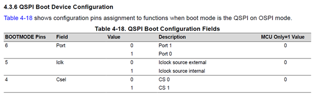
I wish to boot the DRA829J's MCU from QSPI (Normal bootmode).  The OSPI port0 will be connected to a QSPI device using 6pins (DQ0-3, OCLK and SS) What does the lclk pin config do here?.  I'm thinking I need to set it to 1 (internal) so the OCLK is sourced from the OSPI module internally to drive the QSPI?.

thanks

  • Hi,

    Would it be possible to get an answer to this?.

    thanks

  • Stephen,

    Please see errata i2307 Boot: ROM does not properly select OSPI clocking modes based on BOOTMODE which addresses the ICLK setting. 

    Use internal.

    Kevin

  • i2307 Boot: ROM does not properly select OSPI clocking modes based on BOOTMODE

    Details The ROM bootloader only selects an internal loopback mode for SPI/QSPI/OSPI/xSPI
    boot, regardless of the Iclk field value selected by the BOOTMODE pins (see the device
    specific TRM for BOOTMODE pin mappings), which is intended to allow the user to
    choose an internal or external clocking method. This results in less flexibility in board
    topology in customers designs. Customers intending to use the external board loopback
    mode could see timing issues in ROM boot because the external loopback clock is not
    being used.


    Workaround The topology of the OSPI design must conform to the design guidelines for "No
    Loopback" mode, which is found in the device specific datasheet, section "Applications,
    Implementation, and Layout". The guidelines for "External Board Loopback" cannot be
    used.