This thread has been locked.

If you have a related question, please click the "Ask a related question" button in the top right corner. The newly created question will be automatically linked to this question.

TMS320C6657: How to do a simple I2C Write/Read using the digital loopback

Part Number: TMS320C6657


Hi,

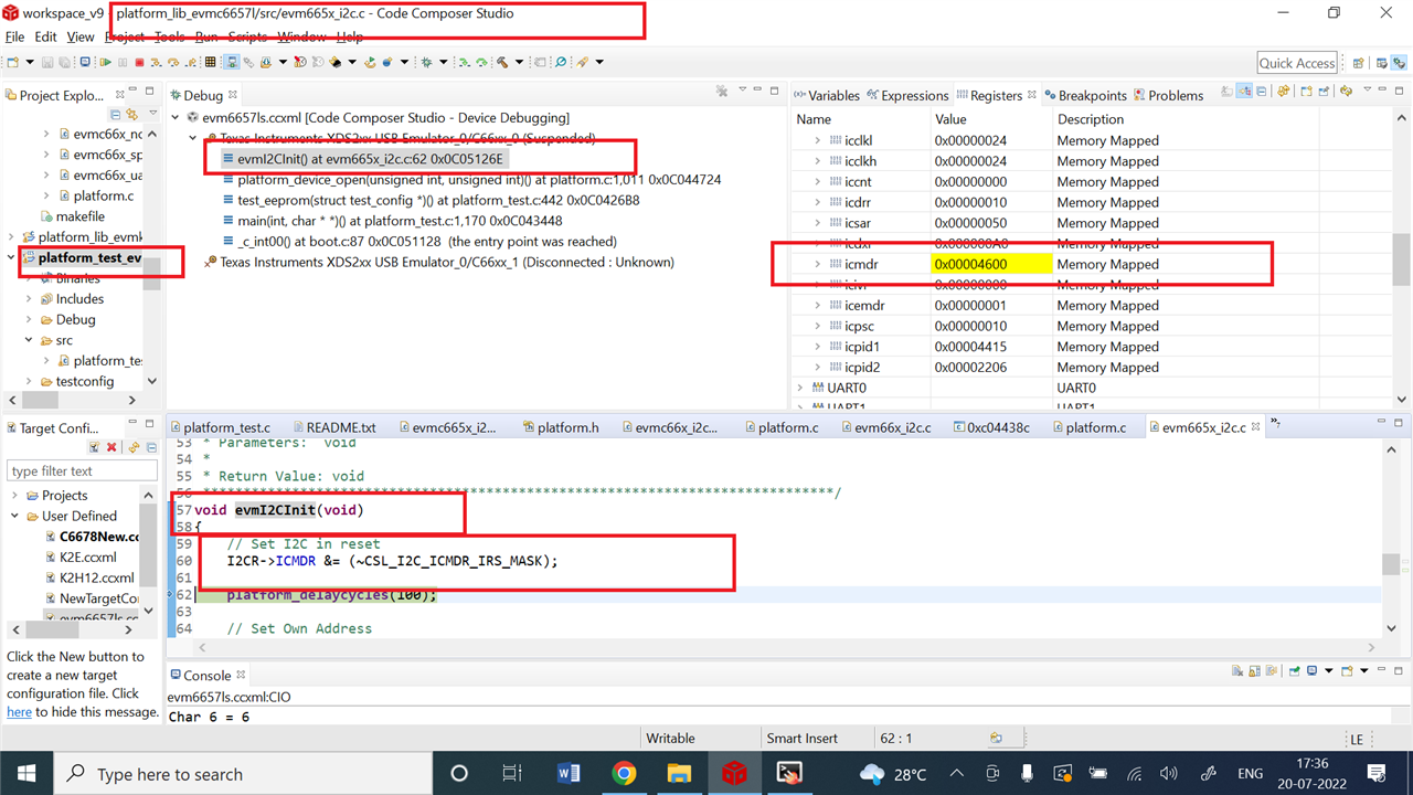
I'm trying to create an I2C driver and I am trying to test it through the digital loopback. I am using the platform_lib_evmc6657l I2C and I2C_eeprom as an example and set the digital loopback (DLB in ICMDR) so I can view the ICDRR to verify if the value was written to correctly. 

I'm having trouble with the write function as I am expecting the value to be in ICDRR, but when I step through it, nothing is being written to that register.

I first start by initializing the I2C by calling evmI2CInit() in evm665x_i2c.c. Then inside evmc665x_i2c_eeprom.c, I change the function i2cEepromWriteBlock() so that it sets the DLB when it also sets the start bit. From there, I keep everything else the same.

Is there something that I am missing for the digital loopback?

Thank you

  • Cynthia,

    Rajan is working on your posts.

    He will post his response, as early as possible.

    Regards

    Shankari G

  • Cynthia,

    I do not see any issues, in the I2C register values...when I run the Platform test....

    Are you able to run the Platform test code successfully on the C6657 EVM?.

    Because, the Platform test includes the test routine for the I2C-EEprom using the "test_eeprom".

    I am able to access the I2C registers and visualize the values of them.

    During EEPROM read and write, able to see the appropriate values on the ICDRR, IMDXR registers too......

    During read and write of EEPROM 

    ==============================

    Regards

    Shankari G

  • Hi Cynthia,

    Sorry for the late reply. 

    For digital loopback, as quoted in https://www.ti.com/lit/ug/sprugv3/sprugv3.pdf (Also 8611.sprugv3.pdf)

    "Digital loopback mode bit (only applicable when the I2C is a master-transmitter). This bit disables or enables the digital loopback mode of the I2 C. The effects of this bit are shown in Figure 3-12. Note that DLB mode in the free data format mode (DLB = 1 and FDF = 1) is not supported. 0 = Digital loopback mode is disabled. 1 = Digital loopback mode is enabled. In this mode, the MST bit must be set to 1 and data transmitted out of ICDXR is received in ICDRR after n DSP cycles by an internal path, where: n = ((I2C input clock frequency/module clock frequency) × 8) The transmit clock is also the receive clock. The address transmitted on the SDA pin is the address in ICOAR."

    We have to make FDF bit in ICMDR as "0" and MST bit should be "1" (I2C is a master and generates the serial clock on the SCL pin).

    And data will be received at ICDRR after n cycles (n = ((I2C input clock frequency/module clock frequency) × 8))

    Kindly confirm these settings in your code and check the Digital Loopback works.

    Thanks & Regards,

    Rajarajan U

  • For Master Transmitting and in a NonRepeat Mode, is there a way to stop the STOP bit from generating when the internal data counter counts down to 0? 

  • Never mind, I misread the scope. I was able to transmit! Thank you