This thread has been locked.

If you have a related question, please click the "Ask a related question" button in the top right corner. The newly created question will be automatically linked to this question.

AM5716: MMC2_CLK Stop issue

Part Number: AM5716
Other Parts Discussed in Thread: TPS65916

Hi Experts,

Our customer was developing their system with AM5716, and they are producing more than 100 units, however, customer encountered the freeze-issue recently. It seems  this issue occurred on just only one board. The phenomenon of this issue and what customer analyzed are as follows. From the following information, customer supposes that it’s an individual defect. However, customer would like to know TI’s comments on this issue. Also, they are asking if it is possible to guess the root cause of this issue because customer's mass production is soon.  would you have heard similar issue report so far?

I believe It is tough to consider this root cause, can I have your expert’s advice/comments on this customer’s inquiry, please?

  • MMC2_CLK (# J7 pin) suddenly stops while accessing the eMMC that connected to the MMC2 block. ( Rarely occurs )
  • It seems to be  easy to reproduce this issue when data is transferred for relatively large file sizes (300MB-500MB)
  • Customer has checked all power supply rails, reset and clocks are also connected correctly, and they confirmed there was not any problem.
  • Customer tried to connect LAUTERBACH’s JTAG emulator to AM5716, but JTAG also crashed after a problem occurred. It means, it’s Unanalyzable.
  • It seems that not only MMC2_CLK stopped suddenly , but also the entire AM5716 seemed to be freeze
  • Customer checked the soldering condition with X-ray, there was no problem.
  • When customer replaced this AM5716 with a new one, the problem no longer occurred.

It will be appreciated if you will share your comments on this.

Best regards,

Miyazaki

  • Hi Experts,

    Can I have your advice/comments on this customer's inquiry, please?

    Best regards,

    Miyazaki

  • Miyazaki-san,

    You mentioned customer swapped the failing AM5716 with a new one and the problem no longer occurred, has customer tried the failing AM5716 on a new board to confirm if failure is still present and follows the unit?  

    A few other questions:

    1. When the CLK stopped, are there any supporting register dump or waveforms to show what was happening?

    2. Was failure happening during read or write?  Are there any frequency, voltage, or temperature dependency?

    3. Was failure happening in the middle of a multi-block transfer or single block transfer?  If customer changes the code to run multi-block transfer vs single block transfer or vice versa, can they reproduce the failure using the other command?

    4. Is failure related to certain data patterns?  Since customer can reproduce the issue easily, have they tried all 0s or all 1s to confirm if failure is still present?  Alternatively, it will be beneficial to dump the data during failure so we can look for any data dependency.

    5. System setup info:

    - What speed mode was failure occurring at

    - How many data bits active

    - What SW + revision were being used

    - What is the interfacing MMC device?

    - Are there any errors reported by the MMC host controller?

    Thanks & Regards,

    Shiou Mei

  • Hello Shiou,

    Thank you for your reply. I will ask those question to customer. Once I'll receive their feedback, I'll share them with you.

    Best regards,

    Miyazaki

  • Hi Shiou,

    I received feedback from customer. Regarding swapping-verification, customer is doing the rework now. Once I’ll receive this result, I’ll share this result with you.

    1. When the CLK stopped, are there any supporting register dump or waveforms to show what was happening?

    After this issue occurred, it seems Debugger (ICE) was freeze suddenly. So, they could not get any register dump or waveforms, unfortunately.

    2. Was failure happening during read or write?  Are there any frequency, voltage, or temperature dependency?

    Customer confirmed this failure occurred both read and write, and customer is not sure if there are frequency, voltage, or temperature dependency at this time.

    3. Was failure happening in the middle of a multi-block transfer or single block transfer?  If customer changes the code to run multi-block transfer vs single block transfer or vice versa, can they reproduce the failure using the other command?

    Customer will try to investigate them.

    4. Is failure related to certain data patterns?  Since customer can reproduce the issue easily, have they tried all 0s or all 1s to confirm if failure is still present?  Alternatively, it will be beneficial to dump the data during failure so we can look for any data dependency.

    When customer tried all 0s, it seems this issue never occurred. Regarding all 1s, they have not tried this verification.

    5. System setup info:

    This failure occurred at 48MHz DDR mode, data bits is 8bit Data, they are using eMMC. Regaring errors report, they are checking it now.

    And then, regarding AM571x’s errata(www.ti.com/.../sprz436 ) “i878 MPU Lockup with Concurrent DMM and EMIF Accesses”, I received  additional questions. When customer tried to do this workaround, this issue was almost resolved (but,  Not completely). So, they would like to know more detail this issue.

    • The workaround with MPU_MA register is described, but it seems that there is no detailed information on this register. If possible, could you clarify it, please?
    • There is the description that is “Issue is seen to come when there is a heavy memory access through the MPU L3 path”. So, customer is asking how much memory access the issue goes away. It may be difficult to answer it, but, can I have your advice, please?

    I really appreciate your strong supports.

    Best regards,

    Miyazaki

  • Hi Experts,

    We have several additional questions.

    • When the internal operating frequency of the MPU was fixed from 1.5GHz to 1.0GHz, the issue improved at room temperature.
      In addition, issue are unlikely to appear at 1.5GHz, data is All "0", and at room temperature, but when the zone temperature of Sitara is set to about 70 degrees C, the incidence of issue has increased. (70 degrees C of 1.0GHz has not been tested yet)
      Are these related to the frequency dependence and temperature dependence of the first question 2.?
    • Please tell us about the following, which is explained in the errata i878.
      "With this MPU_MA register setting, we found that three different high-load application scenarios that previously reproduced the problem worked well in long-term testing."
      What are the three scenarios, test duration, and reduction rates?
    • I interpreted it as a workaround for the errata i878 by doing the following two things, is that correct?
      1) The MPU should avoid use of the L3 Interconnect path via the MPU
      2) 0x482AF400 | = 0x6.
      If it is correct, please tell me how to do 1).
    • Regarding the first question 4, "Data dependency", the symptom was more likely to occur in All "1" than in All "0".
    • Please tell me the items that need to be dealt with in the latest errata.

    Thank you for your cooperation.

    Best regards,

    Kadowaki

  • Kadowaki-san,

    Thank you for your sharing further information about this failure.

    Hi Shiou,

    Can we have further advice/comments on those inquries, please?

    I'm sorry for rusing you, but, it is really appreciated your quick reply because  the production for this system is stopped.

    Best regards,

    Miyazaki

  • Hello Shiou,

    I’m sorry to rush you. but, can we have your expert’s comments on this, please ?

    From their verification so far, they are feeling that this failure is highly dependent on internal operating frequency (CPU frequency). Customer is hoping comments that there is not any problem if they use AM5716 at something like 1GHz frequency. But, it may be difficult.

    Best regards,

    Miyazaki

  • Miyazaki-san, Kadowaki-san,

    I looked more into details of the i878 errata and here are the answers to your questions:

    Q: Are these related to the frequency dependence and temperature dependence of the first question 2.?

    [SH]  Yes, looks like your failure behavior is changed with frequency and temperature, that will indicate frequency and temperature dependence. 

    Q: Customer does not understand what three different high-load application scenarios means. Could you clarify test duration and reduction rates?

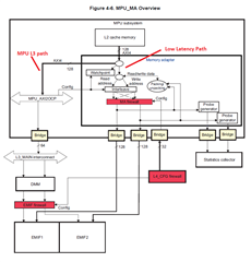
    [SH]  The tests were run with concurrent memtester + MPU stress test; unfortunately I cannot share details of the test setups.  Essentially the MPU_MA is composed of two different paths to EMIF, the right hand side one goes through interleave and is the low latency option called out in the errata.  The left hand side one goes through MPU_AXI2OCP and is referenced as MPU L3 path in the errata.  

    If both of these paths are active simultaneously, then errata i878 may happen.  As a result, the workaround is to avoid using the left hand path (MPU L3) path entirely.  All access should instead be re-routed through proxy access from DMA/IPU/DSP.  The MPU low latency path can still be used.

    As you mentioned, 0x482AF400 Bits [2:1] should also be set to achieve a value of 0x482AF400 |= 0x6. This register info is internal to TI, as such is not disclosed in the Errata.  However, it is related to MPU_MA and the setting should assist with reducing the occurrence of the issue.

    This figure can be found in the AM5716 TRM under Figure 4-6.


    It does sound like customer issue is no longer reproducible after following the workaround, please let me know if this understanding is correct, and if customer use case aligns with this errata description.

  • Miyazaki-san,

    Please also confirm which SW and revision customer is using.

  • Hello Shiou-san

    Thank you for your comment.
    I write additional information and questions.

    Additional testing has shown that it works fine up to 1.4GHz.
    It was also found that the problem occurrence rate increases as the frequency gradually increases from 1.4GHz to 1.5GHz.
    Does this mean that it is 'frequency dependent'?
    Does it mean that lower frequencies are less likely to cause problems?
    Therefore, we decided to stop using it at 1.5GHz and use it at a maximum of 1.4GHz. Is this judgment correct?

    I would like to comment on Shiou-san's last sentence.
    The only workaround we have implemented is register changes. In that case, it was not very effective.
    We have only confirmed that lowering the operating frequency is effective.
    Please tell me the other workaround, 'do not use MPU_L3 path'.

    The SW we are using is 'PROCESSOR-SDK-LINUX-AM57X — Linux Processor SDK for AM57x'.
    The version is 06.03.00.106.
    Is it possible to take measures without using the MPU_L3 path by updating it to the latest version?

    Best regards,
    Kadowaki

  • Kadowaki-san,

    A few actions to isolate your failure and understand the behavior better:

    1. Please confirm your operating condition and measure the voltage domains (VD_CORE, VD_MPU, VD_RTC, etc) to make sure they are operating correctly at the desired operating mode.

    2. Boost the voltage on the failure device and confirm if increasing the voltage also affected the failure.

    Let us know the results of these two actions, thank you!

  • Hello Shiou-san,

    Thank you for your quick response.

    About question 1
     Each voltage domain was operating in the desired mode.
    About question 2
     There is a description of boost, but please tell me the specific value. Is it 1.25V + 2%? Is it 1.5V?
    If boosting solves the problem, what is the cause?

    Best regards,
    Kadowaki

  • Kadowaki-san,

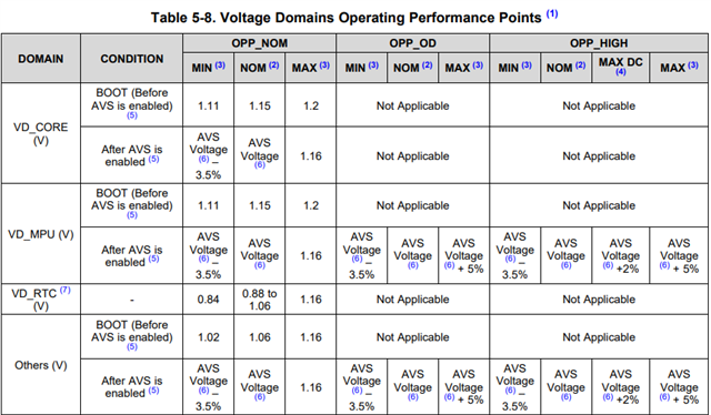
    Can you try the maximum voltage values defined for each domain, then remove the changes one domain after another to isolate which domain voltage is affecting the failure?  The max voltage is defined as 1.2 V on VD_MPU and VD_CORE; you can reference the datasheet for the other domain specifications. 

    What OPP is customer operating in?

    If boosting the voltage solves the issue, it is still hard to say what is the root-cause.  There might be voltage dips in the voltage rails on the failing board.  To verify this, connect an oscilloscope to the rail on the SoC side and monitor for any possibilities a voltage is observed less than the required operating level.  

  • Shiou-san

    Thank you for your comment.

    We will try voltage verification for each domain.
    We are using OPP_HIGH.
    By the way, about "The max voltage is defined as 1.2 V on VD_MPU and VD_CORE;"
    According to SPRS957I, the maximum value of VDD_MPU is 1.25V when using OPP_HIGH, according to Table 5-8 and note (6). Is that correct?

    postscript
    I will be on summer vacation from 10th Aug., so please forgive me for the late response.

  • Hello Kadowaki,

    Latest datasheet version does confirm OPP_HIGH maximums to be 1.2V for VD_CORE/VD_MPU:

    Regards,

    Marco

  • Hello Marco-san,
    Thank you for showing the data sheet.
    We have also seen the table you provided, but we have two questions.

    Q1: Isn't the maximum voltage "1.25V" instead of "1.20V"?
     According to note (6), the AVS voltage at OPP_HIGH is 1.05--1.25V.
    In fact, our set is operating at 1.25V when AVS is set. (Please check the wevwform below.)

    Also, We tried to set 1.26V and 1.27V in the voltage change confirmation, but We could not set it to those voltages.

    Q2: Can't the AM5716 to TPS65916 (PMIC) be set to 1.26V or higher?

    Best regards,
    Kadowaki

  • Kadowaki-san,

    @OPP_HIGH:

    VD_CORE: Max at boot: 1.2V

                       Max after enabling AVS: 1.16V

    VD_MPU: Max at boot: 1.2V

                     Max after enabling AVS: AVS Voltage + 5%

    The AVS voltage level specific to the device can be read from the STD_FUSE_OPP Registers, and should be within the range 1.05-1.25V. Please see below for VDD_MPU OPP_HIGH register/bitfield to read (taken from TRM).

    Please confirm what this value is read as. STD_FUSE_OPP_VMIN_MPU_4 + 5% should be the value configured on the PMIC, and my understanding is that this value should not exceed 1.25V.

    Regards,

    Marco

  • Hello Marco-san,

    Thank you for your reply.

    We checked the register (STD_FUSE_OPP_VMIN_MPU_4) and it is 1.25V (0x04E2).

    Therefore, we were requested by Mr. Shiou Mei Huang,
    ”2. Boost the voltage on the failure device and confirm if increasing the voltage also affected the failure.”
    As for , it cannot be raised any further.

    Q1: From the above results, We understand that the maximum voltage of AVS has been reached, so we cannot raise the voltage.
           Is this understanding reasonable?

    Conversely, I set VDD_MPU to 1.05V, but the symptoms did not change.
    This led us to recognize that the symptoms of errata i878 are independent of DC voltage.

    However, the increased capacitor capacity of the VDD_MPU and the enhanced board wiring of the VDD_MPU (referred to SPRAC 76 D in the application manual) improved the symptoms of the problem.
    We will proceed with the design with this countermeasure.


    Best regards,
    Kadowaki

  • Hello Kadowaki-san,

    Thank you for confirming that information.

    As for setting the voltage higher than the specified maximum, it is most probably being blocked in software (despite the PMIC being able to supplying voltages higher than 1.25V). This could be disabled, but adjusting capacitance is the more straightforward route.

    The app note on power distribution networks you mentioned (SPRAC76D) is certainly a good resource to use, as improved routing and capacitor selection would be the next debug steps here anyway. Violating PDN guidelines can cause voltage dips from capacity issues or noise to happen.

    Has the issue been resolved/can the ticket be closed?


    Best regards,

    Marco