This thread has been locked.

If you have a related question, please click the "Ask a related question" button in the top right corner. The newly created question will be automatically linked to this question.

TDA4VM how to compile & run standalone example Loading through SD Card.

Hi, TI

There are three standalone examples located ti-processor-sdk-rtos-j721e-evm-08_01_00_13/pdk_jacinto_08_01_00_36/packages/ti/drv/dss/examples/

Now, want to use this to test output by using DSI Interfce.

used this command under dir <ti-processor-sdk-rtos-j721e-evm-08_01_00_13/pdk_jacinto_08_01_00_36/packages>,

source pdksetupenv.sh

# make -s all PDK_SOC=j721e -j32 

But cannot find any file(s) named dss_colorbar_testapp_ OR _display_testapp.

1. Please tell me How to complie & run it by loading through SD Card ?

Best Regards,

Murphy

  • Hi Murphy,

    In order to run DSS on DSI output, please follow below steps,

    1, Enable DISP_APP_TEST_DSI in ti-processor-sdk-rtos-j721s2-evm-08_00_04_04\pdk_j721s2_08_00_04_09\packages\ti\drv\dss\examples\dss_display_test\dss_display_test.h file.

    2, You could change the test params DISP_APP_USE_TEST_PARAMS to DISP_APP_YUV2_2 for DSI output. or can keep same RGB32 input format.

    3, Go to pdk_jacinto_08_02_00_21/packages/ti/build folder

    4, run "make -s dss_app_utils CORE=mcu2_0 BUILD_PROFILE=release"

    5, run "make -s dss_display_testapp_freertos CORE=mcu2_0 BUILD_PROFILE=release"

    6, The generated binary would be available pdk_jacinto_08_02_00_21/packages/ti/binary/dss_display_testapp_freertos/bin/j721e_evm/dss_display_testapp_freertos_mcu2_0_release.appimage. Copy this binary as app in the SD card.

    7, Copy SBL and TIFS to the SD card

    8, Insert the SD card on the Board and boot the board.

    Regards,

    Brijesh

  • Hi Brijesh,

    In order to run DSS on DSI output, please follow below steps,

    The experiment was successful and the log is as follows. 

    Note:
    EVM UART
    1. 4xUART to USB port for Main uarts
        Port0 from this is used this for Linux, RTOS UART terminal from A72
    2. 2xUART to USB port MCU domain uarts
        Port0 from this is used for DMSC UART
        Port1 from this is used for MCU R5F UART
    
    < RTOS UART terminal from A72 >
    DispApp_init() - DONE !!!
    DSS display application started...
    Display create complete!!
    Starting display ... !!!
    Display in progress ... DO NOT HALT !!!
    Underflow did not occur
    Underflow did not occur
    Sync Lost did not occur
    Display delete complete!!
    Number of frames = 2000, elapsed msec = 33366, fps = 59.94
    DispApp_deInit() - DONE !!!
    DSS display test Passed!!


    Next I will test the DSI, so I made below changes. The main purpose is to measure the waveform of DSI-TX when the image is output. 

    But The serial port has no output after power-up. Wonder if it's already started? Or this must be debugging with CCS !!

    < Port1 from this is used for MCU R5F UART >
    SBL Revision: 01.00.10.01 (Jul 15 2022 - 13:53:42)
    TIFS  ver: 21.9.1--v2021.09a (Terrific Lla
    SBL Revision: 01.00.10.01 (Jul 15 2022 - 13:53:42)
    TIFS  ver: 21.9.1--v2021.09a (Terrific Lla
    Sciserver Built On: Feb  2 2022 12:39:09
    Starting Sciserver..... PASSED
    GTC freq: 200000000
    
    < nothing log on A72 uart >

    Regards,

    Murphy

  • Hi Murphy,

    But The serial port has no output after power-up. Wonder if it's already started? Or this must be debugging with CCS !!

    If you are running it on mcu2_0, the output will be on the main domain uart console. Mcu domain uart console will just show messages from SBL. 

    By default the output of DSI goes to the UB943 serializer on the EVM. It does not goto DSI-TX output. So please check if the probe point is correct.

    Regards,

    Brijesh

  • Hi Brijesh

    Next I will test the DSI, so I made below changes. The main purpose is to measure the waveform of DSI-TX when the image is output. 

    #define DISP_APP_USE_TEST_PARAMS (DISP_APP_YUV2_2)//(DISP_APP_BGRA32_1) zpf

    /* Load buffers runtime for RGB24 and YUV formats */
    #define DISP_APP_LOAD_BUFFERS_RUNTIME (1U)//(0U) zpf

    /**< Enable DSI output, configures DSI for 1280x800 resolution and
    * uses LCD AUO display for displaying YUV422 image */
    #define DISP_APP_TEST_DSI (1U)//(0U) 

    1. But after making changes, main uart shows nothing log.

    2. Did you mean UB941 serializer? Probe on UB941 clk & data lane, nothing show on scope.

    Rrgards,

    Murphy

  • Hi Murphy,

    Any specific reason for enabling input? Because i think input needs to be provided via CCS console and in this case, you are using uart console. 

    Can you try disabling this option?

    2. Did you mean UB941 serializer? Probe on UB941 clk & data lane, nothing show on scope.

    Can you please probe the lines when DSS application is running? 

    Regards,

    Brijesh

  • Hi Brijesh,

    #define DISP_APP_USE_TEST_PARAMS (DISP_APP_YUV2_2)//(DISP_APP_BGRA32_1) 

    /* Load buffers runtime for RGB24 and YUV formats */
    #define DISP_APP_LOAD_BUFFERS_RUNTIME (1U)//(0U) 

    /**< Enable DSI output, configures DSI for 1280x800 resolution and
    * uses LCD AUO display for displaying YUV422 image */
    #define DISP_APP_TEST_DSI (1U)//(0U) 

    The reason why to set these params is to enable DSI-OUTPUT from the point of view of the source file(pdk_jacinto_08_01_00_36\packages\ti\drv\dss\examples\dss_display_test\dss_display_test.c in function DispApp_runTest --> DispApp_configDctrl --> #if (1U == DISP_APP_TEST_DSI) ) and also refer to this link. <e2e.ti.com/.../tda4vmxevm-dsi-pixel-clock-dss_display_test

    Can you please probe the lines when DSS application is running? 

    After disabling these params, Just leave it as default setting. Recompiled !

    Probe on UB941 clk & data-lane, There is no waveform from power-on till the end of DSS application finished(kepe 0V).

    DispApp_init() - DONE !!!
    DSS display application started...
    Display create complete!!
    Starting display ... !!!
    Display in progress ... DO NOT HALT !!!
    Underflow did not occur
    Underflow did not occur
    Sync Lost did not occur
    Display delete complete!!
    Number of frames = 2000, elapsed msec = 33366, fps = 59.94
    DispApp_deInit() - DONE !!!
    DSS display test Passed!!

    Regrads,

    Muprhy

  • e2e.ti.com/.../tda4vmxevm-dsi-pixel-clock-dss_display_test

    Thread-lin: e2e.ti.com/.../tda4vmxevm-dsi-pixel-clock-dss_display_test

  • Hi Brijesh,

    As you suggested & CCS-Debugging for loading image.

    In order to run DSS on DSI output, please follow below steps,

    1, Enable DISP_APP_TEST_DSI in ti-processor-sdk-rtos-j721s2-evm-08_00_04_04\pdk_j721s2_08_00_04_09\packages\ti\drv\dss\examples\dss_display_test\dss_display_test.h file.

    2, You could change the test params DISP_APP_USE_TEST_PARAMS to DISP_APP_YUV2_2 for DSI output. or can keep same RGB32 input format.

    3, Go to pdk_jacinto_08_02_00_21/packages/ti/build folder

    4, run "make -s dss_app_utils CORE=mcu2_0 BUILD_PROFILE=release"

    5, run "make -s dss_display_testapp_freertos CORE=mcu2_0 BUILD_PROFILE=release"

    6, The generated binary would be available pdk_jacinto_08_02_00_21/packages/ti/binary/dss_display_testapp_freertos/bin/j721e_evm/dss_display_testapp_freertos_mcu2_0_release.appimage. Copy this binary as app in the SD card.

    7, Copy SBL and TIFS to the SD card

    8, Insert the SD card on the Board and boot the board.

    xxds110 need to update the firmware !!! But XDS110SupportReadMe.pdf said 

    How to fix this ?

    Regards,

    Murphy

  • Hi Murphy,

    Sorry, could not understand. Are you trying to update the xds110 firmware? It should get auto updated, when clicked on on the dialog box..

    Also is this again to check the DSI output on EVM? I thought you were able to run this example in vision apps, with smaller resolution, isn't it? Could you please help me understand the intent of this exercise? 

    Regards,

    Brijesh

  • Hi Brijesh,

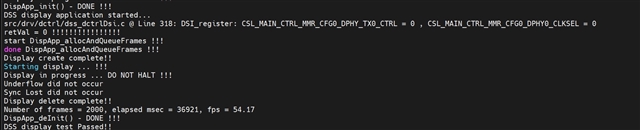
    Boot from SD card. log as below. Probe on UB941 DSI-pin clk & data-lane0/1, None of them have a waveform !!!!!

    DispApp_init() - DONE !!!
    DSS display application started...
    src/drv/dctrl/dss_dctrlDsi.c @ Line 318: DSI_register: CSL_MAIN_CTRL_MMR_CFG0_DPHY_TX0_CTRL = 0 , CSL_MAIN_CTRL_MMR_CFG0_DPHY0_CLKSEL = 0
    Display create complete!!
    Starting display ... !!!
    Display in progress ... DO NOT HALT !!!
    Underflow did not occur
    Sync Lost did not occur
    Display delete complete!!
    Number of frames = 2000, elapsed msec = 36921, fps = 54.17
    DispApp_deInit() - DONE !!!
    DSS display test Passed!!

    So tried to use CCS-Debug to load a image. Encountered this issue <required to update xds110 firmware>!

    In fact, Both Boot From SD Card and debugging on CCS are aimed at one purpose to probe TDA4 DSI output data format Whether it contains the required information<VSA+VBP+VFP>.

    Regards,

    Murphy

  • Hi Brijesh,

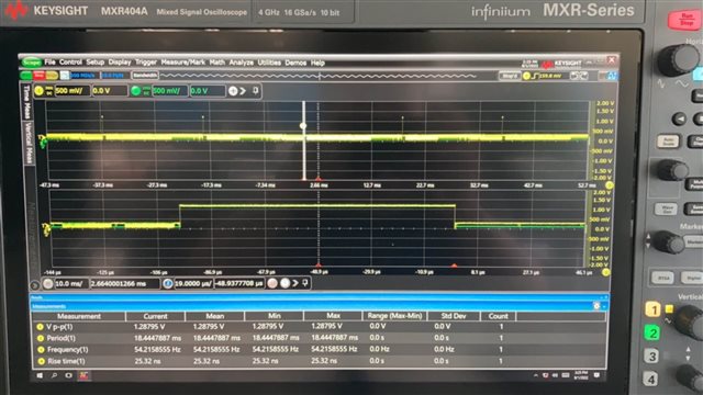
    Here is the DSI-Tx test waveform & log !

    Regards,

    Murphy

  • Unlocking this ticket. Please update latest status on this ticket.