This thread has been locked.

If you have a related question, please click the "Ask a related question" button in the top right corner. The newly created question will be automatically linked to this question.

How to burn a program into SPI flash memory on the c6748 EVM board

Other Parts Discussed in Thread: OMAPL138, OMAP-L138

How to burn a program into SPI flash memory on the c6748 EVM board? 

I've been struggling with that question for several days, with no success.  For such a simple thing, it's turning into a lengthy research project, and I can find no clearly described solution.  I feel like someone trying to open a combination lock -- it's easy if you already know the combination, but otherwise virtually impossible. 

I've found three different software bundles, and don't know which one to use.

OMAPL138_DSP_Flash_Utility_01.00.00.01
OMAP-L138_FlashAndBootUtils_2_30
OMAP-L138_FlashAndBootUtils_2_31

The documentation (and the wiki page) is cryptic, incomplete, and mistakenly assumes I know things. 

This simple process apparently requires a bewildering array of software packages, any one of which turns into a research project.  Here is a list:

  • Microsoft .NET framework
  • Hex6x.exe (I finally stumbled across a manual for that program -- 27 pages (!) buried deep within the Assembly Language Tools manual).
  • Or am I supposed to instead use HexAIS_OMAP-L138.exe?
  • A terminal program of some kind
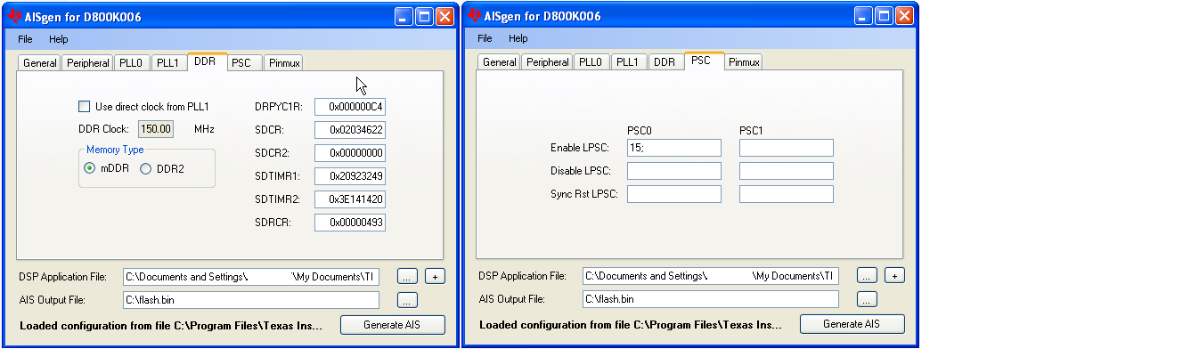
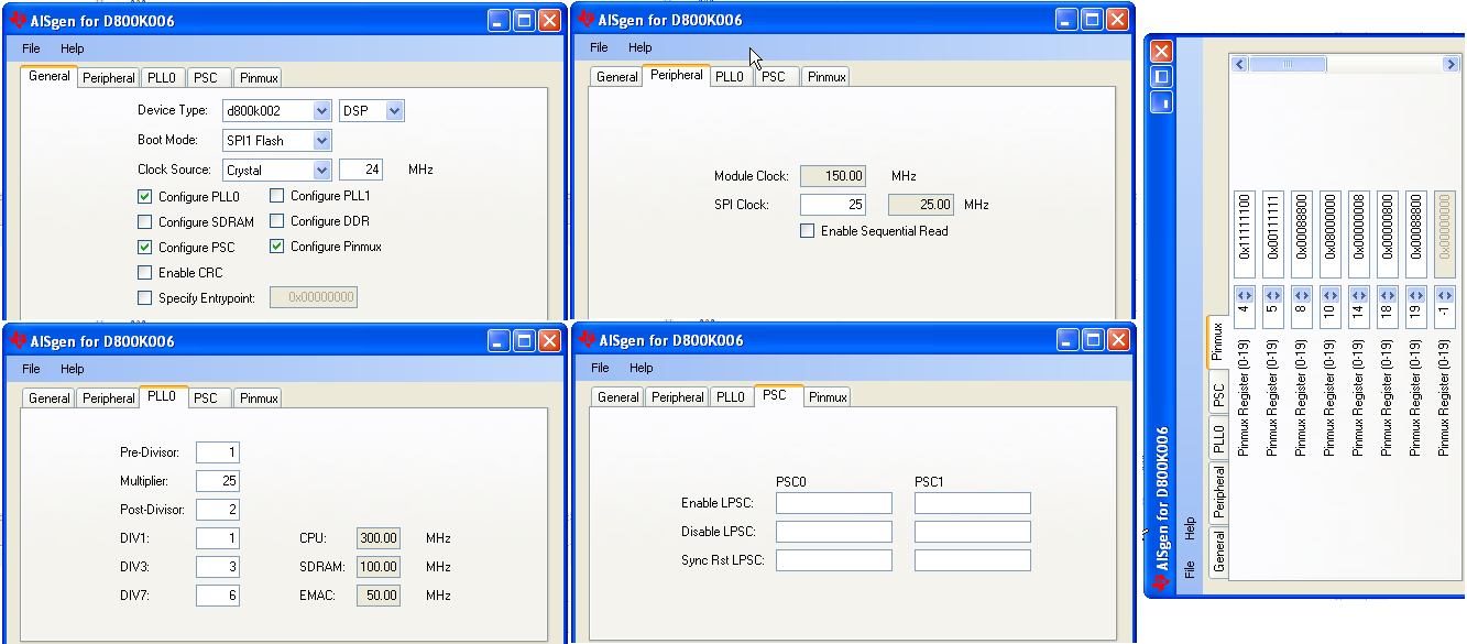
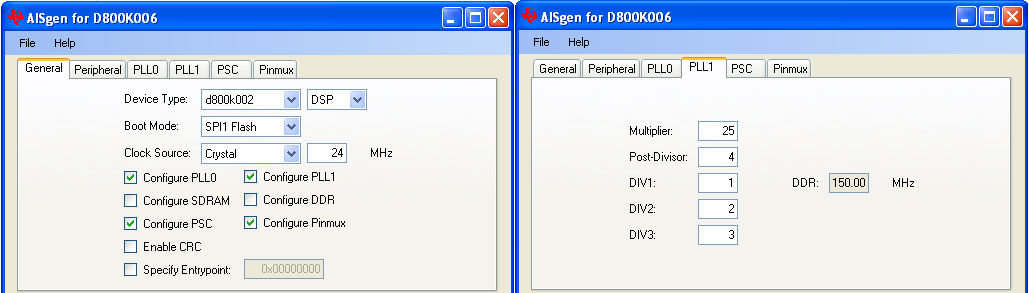
  • An AIS wrapper of some kind (whatever that is)...
  • A UBL of some kind (whatever that is)...
  • Apparently two simultaneous communication cables linking the target board with the Host PC:  a UART serial connection, plus a JTAG connection.
  • And the software requires many option switches that are undefined. 
  • An application image entry point address (whatever that is)
  • An application image load address (whatever that is)


It's a mess.  (Do I sound frustrated?) Can someone straighten out a clear path to success? (If possible, a method that does not use the UART port.)

Why can't CCS simply take the program currently running on the target board, and burn it into the on-board flash memory? This would seem to be a simple process......

  • Walter,

    Sorry for the confusion/frustration.  You've come to the right place!  Let me try to clarify.  If I understand you correctly you are doing everything on the EVM.  That being the case you will not be required to rebuild the flashing tool itself.  Therefore you will not require the Microsoft C# compiler.  You will, however, still require the latest .NET framework (4.0) to run the tool itself from the command line.

    So in a nutshell (gleaned from here):

    • Grab OMAP-L138_FlashAndBootUtils_2_31
    • Install Microsoft .NET Framework 4.0
    • Hookup EVM to PC with serial cable.
    • Setup the EVM for UART boot.  Verify by opening TeraTerm or Hyperterminal and you should see "BOOTME" when you power on the EVM.
    • Make sure TeraTerm/Hyperterm is closed so that the flash utility can access the serial port!
    • Run this command:
      • sfh_OMAP-L138.exe -flash <UBL binary file> <u-boot binary file>
    • Change boot switches back to SPI boot.

    The CCS/JTAG method is an alternate method, i.e. you do not need JTAG and UART connected simultaneously.

    UBL is the "user bootloader".  You may also see the term RBL which is ROM bootloader.  So when you power up the device the first thing to execute is RBL, which loads UBL, which loads u-boot, which loads Linux.  As you can imagine, each of these loaders will require that the thing they are loading is formatted such that it can be parsed and placed into the proper memory location.  In the case of the RBL, the format it understands is called AIS ("Application Image Script").  In other words, it expects the UBL image to be formatted as AIS.  So part of the UBL build process involves taking your output and running it through HexAIS (included in OMAP-L138_FlashAndBootUtils_2_31) in order to properly format it.

    I hope that helps bring some clarity to things.

    Best regards,
    Brad

  • Mastermind Brad, of the great and noble Griffis clan,

    You're instructions are very helpful.  I'll be back soon with the results.  In the meantime, I have a related question. 

    These are the steps in programming my C6748 SOM parts:

    1. unplug the SOM from target board
    2. plug the SOM into EVM board
    3. program the SOM
    4. unplug the SOM from EVM board
    5. plug the SOM into target board

    Steps 1, 2, 4, & 5 can be eliminated if I use only the JTAG port on my target board to program the SOM.  Seems simple, yes? Could you give a few more hints on how to do that?  Since the JTAG and SOM are identical (whether using these on the EVM or on the target board) I presume the flashing tool will not need to be rebuilt or altered in any way.  Am I correct in that?


  • Hi Walter,

    I assume you have seen this wiki: http://processors.wiki.ti.com/index.php/Serial_Boot_and_Flash_Loading_Utility_for_OMAP-L138

    Can you give some more details on which parts were most unclear so we can improve it? This wiki only deals with flashing data onto the SPI flash. If you want more information on how to take a program you have working in CCS and booting it, this wiki might be more helpful: http://processors.wiki.ti.com/index.php/Boot_Images_for_OMAP-L138

    The serial flasher is intended for use for boards that do not have a JTAG connection, so only a UART serial connection is required. If you have both, then either the serial flasher or the CCS-based flasher can be used.

    Jeff


  • Mastermind Jeff,

    jc-ti said:
    I assume you have seen this wiki: http://processors.wiki.ti.com/index.php/Serial_Boot_and_Flash_Loading_Utility_for_OMAP-L138

    Can you give some more details on which parts were most unclear so we can improve it?

    See my comments at the bottom of that wikipage.

    If you have both [a UART connection and a JTAG connection], then either the serial flasher or the CCS-based flasher can be used.

    I'm confused.  My favored approach would be to avoid the UART connection altogether, and use only the JTAG connection and CCS to flash the SOM.  However, it appears the CCS flasher uses both the JTAG and UART connections.  In any event, the instructions are confusing. 

  • Mastermind Brad,

    Brad Griffis said:
    Run this command:
    • sfh_OMAP-L138.exe -flash <UBL binary file> <u-boot binary file>

    I presume <UBL binary file> is:  ubl_C6748_SPI_MEM.bin

    I presume <u-boot binary file> is MyProject.out   ???

    Or must I convert MyProject.out to MyProject.bin by using HexAIS_OMAP-L138.exe  ???  (Or should I use Hex6x.exe???)


  • Addendum to my previous post:

    When invoking sfh_OMAP-L138 don't I also have to specify

    -targetType C6748 -flashType SPI_MEM

    And must I also specify an application load address?  And an application start address?  Or can the loader already know that or figure it out?

  • UPDATE:

    I made a tiny step forward.

    First I converted MyProject.out to MyProject.a0, using the Hex6x.exe utility.

    (Was I supposed to use the HexAIS_OMAP-L138.exe utility?  I can't get it to work.  It keeps rejecting my file, even when I use the default OMAP-L138.ini file.)

    Then I used the following command:

    sfh_omap-l138 -p COM1 -flash -targetType C6748 -flashType SPI_MEM ubl_C6748_SPI_MEM.bin MyProject.a0

    The software appeared to program the SOM. At least it made no complaints and it reported a success.  However, the software doesn't run in the target board, (even though the same software runs on that same SOM and target board using the debugger).  Perhaps the above command should include an application load address?  Or an application start address?

  • UPDATE:

    I seem to have gotten the HexAIS_OMAP-L138.exe  utility to work, at least it did not complain, so I assume it worked.  Same with the Hex6x utility.  I don't know which one I should be using.    ?

    Then I tried using it with and without telling it the start address.  But either way, I couldn't get the software to run.  I assume I'm not properly loading/flashing/initializing (?) the SOM flash memory, because my software runs on the SOM and target board via the debugger, but not from the flash memory. 

    So there's still something about this process that is mysterious.  Any ideas?


  • Walter Snafu said:
    I seem to have gotten the HexAIS_OMAP-L138.exe  utility to work, at least it did not complain, so I assume it worked.  Same with the Hex6x utility.  I don't know which one I should be using.    ?

    The boot ROM expects to find AIS.  Therefore you must use HexAIS to process your ubl output.

  • Walter,

    I just thought of a great resource for you:

    http://processors.wiki.ti.com/index.php?title=TMS320C64x%2B_DSP_System_Integration_Workshop_using_DSP/BIOS

    The wiki page above contains the complete materials for the 4-day workshops that we teach.  In particular there is a lab on flashing your own program onto the EVM!!!!  If you download the Workshop 5.80 student guide I believe it has instructions on how to flash the 6748 EVM.  (I tried to open it to verify but I'm on a slow connection that was going to take an hour to download the file!)  If you get the 5.90 student guide it has instructions on how to flash the OMAP-L138 EVM (more complicated because the ARM has to wake the DSP).

    The directions for the workshops tend to be very thorough so I imagine you'll find the time more productive.  I apologize for throwing yet another resource at you but I think you'll find this one closer to meeting your expectations.

    Brad

  • Brad Griffis you're a Rock Star!  You gave a wonderful resource with lots of answers to my questions.  The best instructions I've seen so far.  Way better than the wiki-page.  There's no way I would have figured it out from the wiki-page.  The instructions describe how to flash the memory via the CCS and the JTAG port, without any need for the UART serial port hookup.  Nice and clean.  These utilities seem to be the most advanced I've seen. 

    (NOTE:  The alternative method -- the ugly UART method -- requires MS .NET framework 3.5 or later, plus two different utilities that run in an MS-DOS window, and each require .ini files. That method is ugly and awkward.  I hope I can dispense with it.)

    Two comments about the wonderful CCS/JTAG method:

    1. There is one awkward step involved.  When using AISgen to create the flash.bin file, we are instructed to put this file "in the SAME folder" as the project .out file.  Fair enough. Later, when using the SPIWriter program to burn the memory chip, it asks for the full pathname for the flash.bin file.  Again fair enough.  However, it will not work if there are any spaces in the path name.  Solving that is awkward, and this awkwardness could have been prevented: (1) by intructions that avoided this mishap before it happens, or even better, (2) by de-glitching the software to avoid this dinosaur remnant from the old days of MS-DOS.
    2. When trying to burn the flash memory, the console reports, "Doing block erase.Doing block erase. SPI boot preparation was successful!"  However, it never returns with any further message, and as best I can tell it fails at the point, without any message.  I don't know why. 
  • Walter,


    Glad you found the "rock star" info from THE rock star. Brad and I actually work together, so I think he's a rock star too. But to solve the problem, he sent you to my "rock star" page. ;-) I guess even one rock star needs another. Eh Brad? ;-)

    Brad asked me to follow up here with you. I developed the 4-day BIOS workshop which is the wiki page he sent you to above. In previous revs of the workshop, we were using the 6748EVM with the 6748 SOM. We are currently using the OMAP-L138 SOM which requires a bit of ARM code to pull the DSP out of reset.

    Based on the popularity of these topics (and Brad's nudging me along), I extracted the two boot/flash chapters and lab/sol files and put them directly on the wiki:

    http://processors.wiki.ti.com/index.php/C6000_Embedded_Design_Workshop_Using_BIOS

    Your comment #1 above is a good one. You are correct. And, this is NOT in the current instructions, so I will fix that and repost it this week. In the workshop, we don't have any spaces in the dir name, hence the potential conflict when other read this and use it outside of the context of the workshop. I didn't write the SPI_FlashWriter, so I can't fix the dinosaur "no spaces allowed" requirement. But I will feed that back to the author of that program. Thanks. Regarding comment #2, the last message I always get is "SPI boot preparation successful" and then the code goes into a SYS_abort or infinite loop - it's done. I have never had it "fail" to boot after that unless I did something odd in my files - like forgetting to program the PLL, etc.

    FYI - the OMAP-L138 instructions do add the ARM code into the flow, but one other thing you might want to look at is how we program EVERYTHING the GEL file used to. It is a very good detailed procedure how to use the AISgen program - even getting the DDR2 clocked and running. Brad actually helped me quite a bit in that area.

    Hope this helps.

    Cheers,

    Eric

  • Prodigy Eric,

    Thanks for your help.  Since I am getting the "SPI boot preparation successful" message, I thought it was merely "prepared" to flash the memory.  You've now cleared me up on that.  It must have actually succeeded in flashing the memory.  That's good news.

    But my code doesn't run, when it used to run on the debugger.  Yes, I enabled the "NO_GEL" definition, so that isn't the problem.  But you mention something mysterious.  You say "the OMAP-L138 instructions do add the ARM code into the flow".  So perhaps some ARM code is mysteriously being added to my code, and that is causing problems? 

    What do you mean by "the OMAP-L138 instructions"?  I don't recall invoking any instructions specific to the OMAP-L138. On the AISGen tool I selected "DSP" rather than "ARM"?  Am I missing something else?


  • So is Snafu really your last name? Yep and gullible is written on the ceiling. I like it.

    If the Flash Writer says "success", it programmed the flash with the binary image. Often, code will not work when it is flashed because, as you mention, the GEL file set something up that you did NOT in the bin file.

    If you are using the C6748 EVM with the C6748 SOM, I have a procedure which I believe you have already been thru. In fact, your fix is already loaded on the wiki in the pdf file. Wow, what customer service. Honestly, thank you for that feedback. This is what the forums are all about. This procedure does NOT involve any ARM code - it is just the DSP. Simple. To locate your problem, however, you have to do a "diff" of what the GEL file sets up vs. your code (or AIS file). I would bet this is where your problem lies. More on that below.

    The other method is for users of the OMAP-L138 SOM where the ARM gets involved. I was forced into using the OMAP-L138 SOM and therefore forced to figure out how to boot both the ARM and DSP. This requires a small bit of ARM code to wake the DSP. It is not trivial (at least for a prodigy). Those instructions and files are listed on the wiki as well under the heading OMAP-L138 SPI1 Flash Boot.

    However, Brad suggested that I write up a FULL BLOWN AIS file which included EVERYTHING in the GEL file - DDR, PLL0/1, PSCs, etc. So, I did (with his help). You may want to download the pdf file for the OMAP-L138 Flash procedure and pay particular attn to the AIS gen area with all of the screen captures. They are the same for both the 6748 and OMAP-L138. This may help you locate your missing "startup" problem.

    The "no gel" flag in that Logic PD BSL code is ok, but I wouldn't trust it. Brad has always preached "do everything in the bootloader" and he is right. I have since deleted the "if no gel" and NOT used those BSL routines in favor of programming EVERYTHING the GEL file does inside the AIS configuration as documented in the procedure for the OMAP-L138 flash procedure. One HUGE missing piece that the LogicPD BSL code does NOT do (with no-gel) is set up the DDR2.

    Let me know if this helps. The links for the flash/boot materials on the BIOS wiki should be "live" by 7pm mountain time tonite...

    Cheers,

    Eric

  • eric_wilbur said:

    In the workshop, we don't have any spaces in the dir name, hence the potential conflict when other read this and use it outside of the context of the workshop. I didn't write the SPI_FlashWriter, so I can't fix the dinosaur "no spaces allowed" requirement. But I will feed that back to the author of that program.

    I may be mistaken, but I believe that the issue of spaces in filenames is actually a problem with CCS.  Regardless, the problem should be documented as a limitation.

    Regards, Daniel

  • Walter,

    I'm glad to hear things are moving in the right direction now!  Have you tried putting the file name in quotes?  That might resolve the space issue.  If so, perhaps Eric can add a note in his instructions.

    Brad

  • Yo Eric of the Wilbur tribe,

    From viewing the AISgen program, I suspected it can replace both the .GEL file and the NO_GEL coding in the software.  But I wasn't entirely sure, until you told me. The NO_GEL approach sure seemed easy, as it didn't require any deep knowledge on my part -- just flip the switch and it's done.  Or so I thought.  Now I see the AISgen program can do this same function. 

    The question then is how to config the AISgen program. I must get a lot of parameters from somewhere. To do a "diff", or to copy over the .GEL setting to the AISgen,  would require me to dig into a bunch of .gel code, which is pretty ugly.  (Have you read one of those .gel files?  It will roll the eyes back in your head...)

    You refer me to a .pdf file -- I assume that's this one.  Those instructions are super helpful.  Though I have three comments:

    1. Under the AISgen Peripheral tab, I cannot get it to match your screen capture images.  That is, I get:  Module Clock=150.00 MHz,    SPI Clock 50 = 50.00 MHz.  Try it!
    2. When finished configuring AISgen, you may want to recommend we save the config file somewhere.  (I assume we should save it in the same directory with the AISgen.exe file  ?)
    3. Perhaps I don't understand the navigation yet, but I often have trouble locating the proper wiki pages.  It's almost like a separate website, with few links to it from your main ti.com website.  And when I try a "search" for it, the search engine drowns me with lots of cryptic references that I must plow through to find what I'm looking for.  The process of getting to the wiki pages could be smoother. 

    This just in:  I tried the above method, and the console reports failure. 

    P.S.  Yes, Snafu reflects my sense of humor.  I am pestering you all with my problems and woes, and I imagine the people at your Help-desk shouting over the fuzzy-cube walls, "Hey, we got another Snafu on the line!".......  It just seemed appropriate.

  • Ok, so my middle name is FUBAR - are you sure you want to continue getting help from me?  ;-)

    Yes, I have looked at many GEL files. They can be cryptic. But, if you look at the DDR2 settings, for example, they are identical to what you place into the DDR2 settings in the AISgen config file. Yes, it takes a little work, but it beats looking through the data sheets. Although, if you want to CHANGE these settings to something else, well, you're back to the datasheet. Heads sometimes have to spin a bit.

    The pdf you linked to is correct. Although, it is the procedure for the ARM+DSP (OMAP-L138) flash boot. But, this was updated as well to include ALL of the AISgen settings. So, you can combine the procedure for the C6748 and the AISgen configuration from the OMAP-L138 procedure.

    Which AISgen are you using? I am using 1.7c. Are you sure you determined your silicon rev correctly (via the instructions in the pdf)?

    Wow - you caught ANOTHER error on my part. It sure is nice to have someone like you going through these procedures and fixing them for me. ;-)  Try Module Clock = 150MHz as before, but put in 25MHz for the SPI clock. 40MHz might be overclocking it. When I looked at my configuration, I used 25MHz. Not sure where that screen cap came from - but it was certainly ME that put it there. Try 25MHz and see if that works.

    I added the hint to save the .cfg file in a folder. If you download the labs/solution files from that wiki, you can even use the .cfg file I have already filled out for you.

    I don't understand your question #3. Is this referring to the TI navigation to find wiki answers? I use it all the time and usually find what I'm looking for quite quickly. Maybe it's the SNAFU influence...

    Well, FYI, you're well beyond the help desk. I create/deliver DSP and BIOS workshops and live in Colorado. If I yell "over my cube", I'd be talking to the dog. Speaking of that, the dog says "woof...leave my master alone..."

    Hope this helps...

    Cheers,

    Eric

  • Eric,

    Your advice is very helpful, and I feel like I'm close to success.

    I'm using AISgen v1.7c, and I'm sure I correctly determined my silicon rev (from using the debugger to look at the DSP memory address) and set it in AISgen.  I'm following all the directions carefully. 

    Here is another mystery.  I have two boards:  The LogicPD EVM board, and a target board (on which LogicPD had a hand) -- and I'm using the same c6748 SOM on both boards (literally moving it physically back and forth between the two boards).  The LogicPD EVM board has an onboard XDS100v1 emulator, while the target board has an off-board XDS100v2 emulator.  All that looks good. 

    And I figure I should be able to flash the memory using the same method for either board.  (Same SOM with the same flash memory.)  But for some reason, I can successfully flash the SOM on the EVM board, but not on the target board.  Any ideas why? 

    And despite the successful flashing of memory, my software still isn't running, even though it ran fine when loaded from the debugger.  I'm baffled. 

  • UPDATE:

    I'm can flash the memory on my LogicPD EVM board, but not on my target board, even though I am using exactly the same physical SOM on each board, and an XDS100 emulator on each board.  I don't understand why there should be any difference in behavior.

    Also, I can run MyProject.out on the target board via the debugger.  But after I flash that same file into memory (using my EVM board and the previously described method) it no longer runs on the target board.  There is still something about the process I'm not getting right.

    =======

    P.S. Tell the woof the Snafu says "Hi!"

  • Eric,

    I'm still struggling along the snafu trail.  (See my above two posts.)

    I'm now guessing my AISgen config file is incorrect.  So, to double check, I downloaded the AISgen config file (omapl138-arm-dsp-spi-psc_tto.cfg) from your student workshop (Lab Files Rev 5.90 (.rar)), and changed the device from ARM to DSP.  The result is exactly what I've been using already.  So that's not the cause of the problem -- unless there's some other difference between ARM and DSP programming.  ???

    I haven't specified the entry point, as I assume AISgen detects that automatically from the MyProject.out file.  Is that correct? 

    I'm running out of ideas to try.


  • For the LogicPD c6748 SOM, should the AISgen config file select (and then specify) mDDR or DDR2? 


  • All LogicPD SOMs come with mDDR, so please chose mDDR and not DDR2

  • Walter Snafu said:

    I haven't specified the entry point, as I assume AISgen detects that automatically from the MyProject.out file.  Is that correct? 

    That's correct.

    Have you tried using the Debug GEL file after the device fails to boot (or appears to fail to boot)? If that indicates that there were no errors with the boot, then you can assume that your image was loaded and started running. Then you can try loading your program symbols (not the actual program, just the symbols) and trying to see where the CPU is running.  You can even just do some spot checks of memory regions that should contain your code and verify it matches the binary code in your .out executable (you can get this by doing a disassembly on your .out file).

    Regards, Daniel


  • Daniel,

    Thanks for the tip about the Debug GEL file.  Very coolness! 

    The result produces these lines of interest:

    C674X_0: GEL Output: ---------------------------------------------
    C674X_0: GEL Output: |               BOOTROM Info                |
    C674X_0: GEL Output: ---------------------------------------------
    C674X_0: GEL Output: ROM ID: d800k002
    C674X_0: GEL Output: Silicon Revision 1.0
    C674X_0: GEL Output: Boot Mode: SPI1 Flash
    C674X_0: GEL Output:
    ROM Status Code: 0x0000000A
    Description:C674X_0: GEL Output: Invalid AIS sync opcode
    C674X_0: GEL Output:
    Program Counter (PC) = 0x00712120

    The "Invalid AIS sync opcode" looks like its indicating an error of some kind.  Is that the source of my problems?  Also, the program counter is not pointing to any legitimate memory location. 

    Note:  On my EVM board, the memory map is:

       dsp_l2_ram:         ORIGIN = 0x11800000  LENGTH = 0x00040000
       shared_ram:         ORIGIN = 0x80000000  LENGTH = 0x00020000
       external_ram:       ORIGIN = 0xC0000000  LENGTH = 0x08000000
       arm_local_ram:   ORIGIN = 0xFFFF0000  LENGTH = 0x00002000


  • Walter,

    So this tells us you are in the right boot mode, but that the ROM boot loader did not complete.  The program counter is in an abort loop in the ROM. The error condition suggests that the AIS boot image was not correct for some reason.  This could be because the there is a problem with the flash, or the contents of the flash are incorrect. It would useful if you could provide the actual AIS image that you are flashing to the Flash.  I think the issue is most likely to be incorrect flash contents, simply because the flashing tools will do a write followed by a read/verify step.

    Regards, Daniel

  • Daniel,

    Okay, here is the AIS image that I am flashing to the Flash.

    I tried to attach my file (flash.bin) to this post, but your website would not allow it.  (Apparently it doesn't like the .bin file extension.)

    So I renamed it to flash.jpg     When you receive it, you should rename it back to flash.bin


  • Is there any answer on this yet? 

    I need to talk with someone by phone.  It shouldn't be taking 4 weeks to flash a memory.  ~~~~~~~~~~~~~~


  • I have questions about the "AISgen for D800K006" software, particularly the PSC tab.  It don't know how to set the parameters in this tab, and I can't find documentation on it.


  • Walter,

    I apologize, I did look at the file and didn't see anything too strange.  There are two areas that might be causing an issue.  One is the DDR configuration, and one is that you appear to be turning on the DSP power domain using an AIS command.

    The DDR configuration may be an issue for the following reasons.  You are using an original 1.0 silicon sample, and there was an issue with the DDR configuration function in the ROM boot loader (it didn't support mDDR configuration, only standard DDR2).  As a result, for generating AIS images on 1.0 silicon, we use a patch that is loaded at the very beginning of the boot image.  This patch is just a bit of code that is loaded and used instead of the internal ROM function.  When we release a new version of the AIS tools, the patch binary is regenerated, but I'm willing to bet it undergoes limited or no testing, since our test platforms don't typically have that old silicon.  So it is conceivable that the patch function is somehow broken, due to changes in compiler versions, or build setups. SO one option for testing, would be to flash a simple test image that can fit into only internal memory and that does not turn on DDR. If you can get such an image to boot, that may mean the patch functionality has in fact broken.

    Turning on the DSP power domain during boot shouldn't, I think, cause an issue.  But, unless you have a good reason to do so, I would suggest disabling that.

    Regards, Daniel

  • Daniel,

    I tried your first test.  I flashed a simple test image that can fit into only internal memory.  I left the memory settings unchanged.  (because I don't understand what to do with your instructions about "does not turn on DDR".)   It didn't work.

    I don't know how to implement your second test.  How do I disable the DSP power domain? 


  • I have questions about the AIGgen tool (known peculiarly as "AISgen for D800K006").

    I am using the LogicPD C6748 SOM, and the following two screen shots show my current settings of concern.  Am I setting these correctly?  (I can't locate a manual for this AIGgen tool. So I'm in the dark.)


  • On the PSC screen delete the text "15;" so that the box is empty.  That way the boot ROM will not mess with the PSC in terms of turning on the DSP.  Can you post screenshots of ALL the screens?  In particular I wanted to see the main/General screen, but probably seeing all of them would be good.  Make sure you have selected the corrected boot ROM revision.

  • Similarly, on the general tab, remove the check from the "Configure DDR" option to disable the code that does that during boot.

  • Here is a screen capture of the parameters used in my latest (failed) attempt to flash the C6748 SOM.  What am I doing wrong?


  • I ran the debug gel script on my latest attempt at flashing the memory.  Attached is the console report.

  • CORRECTION:  I noticed that PLL1 had somehow come unchecked.  So I ran everything again, this time the same as above, except with the correction to the two screens captured here.


  • Walter,

    Let's simplify things as much as possible and build up from there.

    We assume that the flashing procedures are working correctly, since the flashing tools should be reading the contents back out of flash to verify that the data was flashed correctly.  They would report some kind of error if this last step failed.

    Let's create an AIS boot image that does nothing, as far as configuration goes. So uncheck DDR, PLL, PSC, Pinmux, etc.  We will load a dummy program that does nothing.  When it boots, it should just go to a dummy loop that spins forever.  I'm attaching that executable program in the zip file.

    This is about as simple as we can get it, so we'll make this a building block of anything we do going forward.  If this doesn't work, then we must have something bigger to worry about (and maybe we will revisit our assumption that the flashing procedures are working). If it does work, then we will take the next step of adding back in configuration steps, one at a time, until it stops working. If all of that works, then we will try switching back to an application that you yourself have created.

    Regards, Daniel


    t3_arm.zip
  • Daniel,

    I did all that you instructed.  I don't know what was in your program (t3_arm.out), but it doesn't seem to run.  The program counters stays at: 0x00712120, which appears to be an IDLE instruction. The disassembled code at that point reads:

    0x00712120:   0001E000            IDLE
    0x00712124:   000A                BNOP.S1       0x712120 (PC+0 = 0x00712120),0
    0x00712126:   8C6E                NOP           5
    0x00712128:   3577                STW.D2T2      B10,*B15--[2]
    0x0071212A:   2C6E                NOP           2
    0x0071212C:   BC35                STW.D2T2      B3,*B15[1]
    0x0071212E:   2C6E                NOP           2
    0x00712130:   0503802A            MVK.S2        0x0700,B10
    0x00712134:   0500786A            MVKH.S2       0xf00000,B10
    0x00712138:   0C6E                NOP           1
    0x0071213A:   9506                MV.L1X        B10,A4
    0x0071213C:   E9C0A000            .fphead       n, l, W, BU, br, nosat, 1001110
    0x00712140:   1008A993 ||         CALLP.S2      0x71668C (PC+17740 = 0x0071668c),B3
    0x00712144:   0627     ||         MVK.L2        0,B4
    0x00712146:   1F12     ||         MVK.S1        152,A6
    0x00712148:   10003192            CALLP.S2      0x7122CC (PC+396 = 0x007122cc),B3
    0x0071214C:   00282286            LDHU.D2T2     *+B10[1],B0

    It's a C6748 SOM, (not an OMAP part with an ARM co-processor).  Did you send me code (t3_arm.out) under the assumption it's an ARM co-processor?  (Just checking.)


  • Walter,

    Yes I did in fact send you ARM code.  Here is a DSP version of the same. Sorry.

    Regards, Daniel

    t3_dsp.zip
  • Daniel,

    I tried it with t3_dsp.out, and got the same result. 

    That is, the program counter is at:  0x00712120

    And the disassembled code there is:

    0x00712120:   0001E000            IDLE
    0x00712124:   000A                BNOP.S1       0x712120 (PC+0 = 0x00712120),0
    0x00712126:   8C6E                NOP           5
    0x00712128:   3577                STW.D2T2      B10,*B15--[2]
    0x0071212A:   2C6E                NOP           2
    0x0071212C:   BC35                STW.D2T2      B3,*B15[1]
    0x0071212E:   2C6E                NOP           2
    0x00712130:   0503802A            MVK.S2        0x0700,B10
    0x00712134:   0500786A            MVKH.S2       0xf00000,B10
    0x00712138:   0C6E                NOP           1
    0x0071213A:   9506                MV.L1X        B10,A4
    0x0071213C:   E9C0A000            .fphead       n, l, W, BU, br, nosat, 1001110
    0x00712140:   1008A993 ||         CALLP.S2      0x71668C (PC+17740 = 0x0071668c),B3
    0x00712144:   0627     ||         MVK.L2        0,B4
    0x00712146:   1F12     ||         MVK.S1        152,A6
    0x00712148:   10003192            CALLP.S2      0x7122CC (PC+396 = 0x007122cc),B3
    0x0071214C:   00282286            LDHU.D2T2     *+B10[1],B0


  • Daniel,

    An interesting clue has surfaced.  I'm working with the C6748 SOM, and moving it back and forth between two boards:  the LogicPD EVM board, and the target board (in which LogicPD also had a hand).  I can program the SOM -- without any complaints from CCS -- on the EVM board (via its JTAG port), but for some reason the same process fails on the target board (via its JTAG port), even though they should both be effectively identical (concerning the SOM, and the JTAG interface, and an XDS100 emulator (v1 or v2)).  Perhaps this is a problem to be solved later, but it is a clue.

    So I tried another test. I took the programmed SOM (the same one reported in my previous post) and tried it this time on the LogicPD EVM board.  And I got a somewhat different result!  That's a clue.  The program counter is at:  0x80001C74

    0x80001C74:   00127F0A            EXTU.S2       B4,19,31,B0
    0x80001C78:   2008A120     [ B0]  BNOP.S1       0x80001C70 (PC+16 = 0x80001c70),5
    0x80001C7C:   E2500000            .fphead       p, l, W, BU, nobr, nosat, 0010010
    0x80001C80:   023D0286            LDHU.D2T2     *+SP[8],B4
    0x80001C84:   BC5D                LDW.D2T2      *B15[1],B5
    0x80001C86:   6C6E                NOP           4
    0x80001C88:   B0C5                STW.D2T2      B4,*B5[5]
    0x80001C8A:   2C6E                NOP           2
    0x80001C8C:   023C8286            LDHU.D2T2     *+SP[4],B4
    0x80001C90:   BC5D                LDW.D2T2      *B15[1],B5
    0x80001C92:   6C6E                NOP           4


  • Daniel,

    I should also mention.  I have a simple test program for my target board.  It simply steps three LEDs through a binary sequence. Super simple, and runs entirely from internal RAM (no use of external RAM).  This program runs properly when loaded and run from the debugger.  This same software then flashes correctly -- at least without complaint from CCS.  But it does not run when the same flashed SOM is used in the target board. Something about the flashing process is not working right.


  • Walter,

    The PC and disassembly you show does not match up with the t3_dsp.out test file I sent.  So I agree, something is wrong with the flashing. And if you can't flash, you can't boot.

    So we are back to square one.

    Just to summarize:

    • We have one C6748 SOM, with original 1.0 silicon (d800k002 ROM ID)
    • We have two platforms, one the Logic EVM, one custom platform (designed with help of Logic)
    • We seem to have something in the flash, which will boot when the SOM is on the EVM, but not on the custom board
    • We are flashing the SPI flash of the SOM when it is placed on the EVM, and flashing appears to pass (but I think we both agree it is not really succeeding)

    What tool are we using for flashing? I'll review this entire thread, but if you can answer that and add/correct any details in the above list that you think are relevant, we can make sure we are on the same page.

    Regards, Daniel

  • Daniel,

    I'm using the flashing tool called "AISgen for D800K006". It would seem the best because:

    • It appears to be TI's most recent flashing tool
    • It connects solely through the JTAG port
    • It does not require a serial UART connection
    • It runs conveniently in a window, complete with setup tabs that help step through the configuration process
    • It does NOT require that the configuration details be setup in a cryptic text config file
    • It does NOT require running in a dinosaur DOS window
    • It is the flashing tool taught in the multi-day TI BIOS classes
    • It is the flashing tool for which the instructions seem the most complete

    You write:

    > We seem to have something in the flash, which will boot when the SOM is on the EVM, but not on the custom board

    I wasn't convinced it "will boot when the SOM is on the EVM".  Apparently you discerned that through the clues I gave?  Rather, I only see that the same physical flashed SOM behaves differently on the two boards.

  • Brad Griffis,

    Here is my latest debug gel file.


  • Walter,

    I see you are still getting an invalid opcode error.  As Daniel mentioned the writer utility will verify the code has been written properly.  Therefore it would seem the code has been burned properly.  That said, there could still be an issue in the READING of the AIS image due to the fact that you are reading the image at a different speed than you are writing the image.  In particular I see the SPI is configured to operate at 25 MHz.  I haven't looked at the data sheet for the device you are using, but often 25 MHz is on the edge of what these SPI flash devices can handle.  That said, I recommend creating a new image and setting that speed much lower, perhaps 5 MHz for now.

    One other thing to try is the "enable sequential reads" option for the SPI.  So can you please do the following:

    • Reduce the SPI clock speed to 5 MHz in the GUI.
    • Burn your new image.
    • See if it works, post the corresponding gel output.
    • Turn on the "enable sequential reads" option.
    • Burn your new image.
    • See if it works, post the corresponding gel output

    Thanks,
    Brad

  • Mastermind Brad,

    I did the two test that you instructed:  5 MHz SPI clock, without and then with the "enable sequential reads" option.

    The console reports are both within the attached file.


  • Walter Snafu said:

    I'm using the flashing tool called "AISgen for D800K006". It would seem the best because:

    Walter,

    The AISgen is NOT a flashing tool.  It is a tool to generate the AIS image you wish to flash.  You then need to take the file generated and flash it to the SPI flash on the board.  Are you doing some step beyond running the AISGen tool?

    Walter Snafu said:

    You write:

    > We seem to have something in the flash, which will boot when the SOM is on the EVM, but not on the custom board

    I wasn't convinced it "will boot when the SOM is on the EVM".  Apparently you discerned that through the clues I gave?  Rather, I only see that the same physical flashed SOM behaves differently on the two boards.

    The PC in the EVM case shows the device running from some code in internal Shared RAM, which should only have happened if the boot completed. That was the reason for that conclusion.

    Regards, Daniel

  • Daniel,

    Yes, I'm doing both steps for flashing.  First AISgen, to create a flash.bin file, and then SPIWriter_DSP to actually flash the memory.  I've been thinking of them as a team-combination.  The one requires the other.  Since AISgen is the focus of concern in our case at hand, I've been referring to it in shorthand (perhaps inappropriately) as "the flashing tool". 

    I had looked at three other TI software bundles to flashing.