This thread has been locked.

If you have a related question, please click the "Ask a related question" button in the top right corner. The newly created question will be automatically linked to this question.

TDA4VM: Issues related to configuring AVS

Part Number: TDA4VM

HI TI,

My device:TDV4VM

OS:A core:QNX    ,MCU_R5:AUTOSAR,others cores:TI RTOS

  • 1.We intend to use AVS to dynamically adjust the voltage.However, we only see the AVS voltage set, but we don't see the relevant function to perform the voltage adjustment process, which makes me feel that the voltage is always fixed.

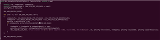
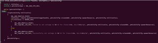
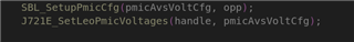
  • 2.J721E_SetupLeoPmicAvs(SBL_OPP_NOM); This function sets the AVS voltage. I also know that there are 4 OPPS, but who decides when to jump from one OPP to another.Is it the software decision or the hardware decision? If it is the software decision, do we need to define the relevant functions ourselves

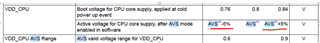
  • 3.How should I configure the OPP, the DATASHEET only gives the value of the voltage in the read and write OPPS, but there is no place to configure the connection between voltage and frequency

Best regard,

guangjie.lin

  • Hi Guangie.Lin,

    Please refer to TRM sections below on power management:

    AVS Adaptive Voltage Scaling is a process for lowering voltage on power rails, only used at startup, to normalize power consumption across all devices.  The API you have called out is the AVS being applied during initialization.

    DFS Dynamic Frequency Scaling can be used to scale frequencies without modifying voltages.

    The OPPs for each device variant are called out in the TDA4VM datasheet.

    Regards,

    kb

  • Hello KB,

    Thanks for your reply. I've read the manual before I ask,but I also have three questions

    • Are AVS valid only during initialization?

    • Whether AVS can automatically adjust the voltage in the relevant voltage domain during system operation

    • Can i switch between different OPPs while running, or i can only switch OPPs only by resetting and restarting ?

    BR

    guangjie.lin


  • Hi Guangjie.Lin,

    AVS should only be run at startup. 

    The code in the SDK RTOS examples, will read eFUSE values for the device and program PMIC accordingly to values which were read, as part of boot, and will not be run again.

    Regarding "switch between different OPP" there is only one defined OPP in the Datasheet  / TRM for the TDA4VM.  Please reference TRM section 5.2.4 Dynamic Power Management for further information, where Dynamic Frequency Scaling may be of interest.

    Regards,

    kb

  • Hello KB,

    I also want to ask whether AVS can be turned off. If it is turned off, will the power supply of VDD_CC also fail

    BR

    guangjie.lin

  • TI recommendation is to leave AVS enabled. 

    The VDD_CC failure/working would be dependent on how the PMIC is programmed without AVS being present.

    Regards,

    kb

  • Hello KB,

    Is there any way to detect the voltage value of VDD_CC? I want to know if AVS actually works and not if it is configured successfully

    BR

    guangjie.lin

  • Hi guangje.lin,

    When possible, probing voltage levels is best approach. Reference the EVM schematics SOM / Common Board and search on VDD_CPU_AVS. Depending on the EVM board revision under test there may be test points that can be probed, or a probe point can be located.  

    From S/W, at runtime or during initialization, the PMIC can be read, and/or the eFuse can be read at anytime.

    An example of outputting the voltage to be programmed to the PMIC is availabe in the SBL boot flow.  This printf would be visible when using the SBL boot with logging enabled and reflects what the device expects the voltage to be set to.

    File: pdk_jacinto_xx_xx_xx_xx/packages/ti/boot/sbl/soc/k3/sbl_soc.c

    The voltage is programmed to the PMIC via I2C, in the same file and similarly logged in SBL boot flow

    File: pdk_jacinto_xx_xx_xx_xx/packages/ti/boot/sbl/soc/k3/sbl_soc.c

    If the desire is to read the programmed value from the PMIC, reference below code, which is a I2C read to the PMIC, then a conversion from PMIC bit value to a voltage.  This should match the probed value on the board, as well as the eFuse value if present.

    File: pdk_jacinto_xx_xx_xx_xx/packages/titi/board/src/devices/pmic/tps65941.c

    Regards,

    kb.

  • Hello KB,

    Thanks for your reply.I also  have some questions to ask you.

    Current status:

    1. We adjust the AVS base voltage in VDD_CC domain from 0.8 to 0.68V according to the AVS voltage recommendation value (0.68~0.72V) given by the hardware department.

    2. Through several experiments, AVS voltage is reduced, temperature is reduced by about 10°, and the load rate of each core is only slightly increased.

    Question:

    1. Whether the proposed AVS voltage of 0.68~0.72V is reasonable, and whether there are any risk points in the future.

    2. Is the default voltage 0.8V too high? Is there any relevant adjustment suggestion?

    Regards,

    guagnjie.lin

  • Hi guagnje.lin,

    The voltages to be used for AVS should be read from the eFUSE registers on the device. 

    Regarding "AVS voltage recommendation value (0.68~0.72V) given by the hardware department".    Is the hardware department being referred to, a TI H/W team?

    Regards,

    kb

  • Hi KB,

     Is the hardware department being referred to, a TI H/W team?

    Not the hardware department of TI, but the hardware department of our company told me that the voltage range was 0.68V~0.72V according to the information in the PMIC data manual.

    Regards,

    guangjiejie.lin

  • Thanks guagnjie.lin,

    The voltages to be used for AVS should be read from the eFUSE registers on the device. 

    The resulting voltage values / PMIC programming, should remain in voltage range specified in the Data Manual.

    Regards,

    kb

  • Thanks KB,

    • I wonder if we are going to do a secondary development based on AVS

    • Because in the pmic and hardware schematic,buck1,2,3 are connected together and the power is supplied to A core. But in the Ti SDK, the code only enables buck1, not enable buck2,3. Should we enable buck2 and buck 3?

    Regards,

    guangjie.lin

  • The J721EVM User guide below, and online Device Manual for TDA4VM, shows Buck 1 & 2 are combined together for VDD_CPU_AVS_REG.    As you have noted, Buck 2 is not enabled in the PDK S/W, which if when extrapolated to the setup you have pasted above, would mean that Buck 2/3 do not need to be enabled.

    TDA4VM EVM User Guide

    TDA4VM Device Manual Section9.1 Power Supply Mapping, leads to TPS65941212-Q1 and TPS65941111-Q1 PMIC User Guide for J721E, PDN-0B (Rev. B) (ti.com)

    Regards,

    kb