Does TDA4VMid(or MidEco) capable of generating 20MHz clock output (recommended accuracy of better than ± 500 ppm) from MCU island? It is required in our design to connect it other SoC.
This thread has been locked.
If you have a related question, please click the "Ask a related question" button in the top right corner. The newly created question will be automatically linked to this question.
Does TDA4VMid(or MidEco) capable of generating 20MHz clock output (recommended accuracy of better than ± 500 ppm) from MCU island? It is required in our design to connect it other SoC.
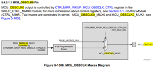
Look at MCU_OBSCLK; it takes a clock from a PLL output divider and then you can divide the clock down.
We cannot generate a clock that tight, but using your crystal and a PLL, this frequency accuracy should be no problem.
One note: if you drive 20MHz across your board, you will create a noticeable 20MHz harmonic in any electromagnetic emissions sweep.
Kevin
Thank you Kevin for your response.
Could you please provide more details about how 20MHz can be generated with the help of simple diagram etc.
Do you mean PLL output on MCU_OBSCLK can be divided externally ?
I see the following in the datasheet
And i am bit confused about the second statement " cannot generate a clock that tight but the accuracy should be no problem". Please clarify.
Please note that our design has external 19.2MHz crystal connected to TDA4VM.
Regd routing of the clock , we will plan to use an inner layer and keep it short and use a series termination to reduce the edge rates.
Praveena,
MCU_OBSCLK can select any of the HSDIV outputs from MCU_PLL{0, 1, 2}. There is a divider on this clock so that it can be divided from its internal frequency.
You will want to start with a frequency that is simply related to 20MHz -- so you might look at MCU_PLL1_HSDIV1 (normally 60MHz) or MCU_PLL1_HSDIV2 (normally 80MHz). My point in referring you to the MCU_OBSCLK pin is that you will need to evaluate which clock you want to use to source the 20MHz.
Clarifying my last response:
- I told you that we cannot generate a 20MHz clock that meets this tolerance. What I meant is that we have an internally generated clock (independent of any external crystal); the frequency is not 20MHz, but more importantly, the tolerance cannot meet the specs.
- In order to meet a 500ppm spec, you need something that is crystal-based, I think. If you had a 20MHz crystal, then, you would simply output that HFOSC clock on the OBSCLK; as is, you have a 19.2MHz crystal and so will need to rely upon the PLLs to multiply this crystal frequency above 20MHz and then divide back down.
- Note that when you look into the TRM, you will find that the 4-bit OBSCLK divider is the programmed binary value + 1 so your range will be /1 to /16. This implies that you need a clock that is a multiple of 20MHz and no greater than 320MHz. Look at the way your clocks are configured and choose something that meets this requirement.
Kevin
Many thanks Kevin!
Per your reply, could you please confirm that:
1. with the current 19.2MHz external crystal on WKUP_LFOSC0_XI/XO, it is impossible to obtain a 20MHz, 500ppm CLK output, right?
2. in order to have a 20MHz, 500ppm CLK output, the only option is to have a 20MHz external crystal on WKUP_LFOSC0_XI/XO, and then output the 20MHz directly at OBSCLK, right?
3. if yes in #2, does IT has a recommended/validated 20MHz part?
4. if changing the external crystal from 19.2MHz to 20MHz, are there any big impacts to other TDA4 circuits, sw/driver etc.?
Best regards!
Hi Kevin,
Just would like to clarify several points you have here:
1. "MCU_PLL1_HSDIV1 (normally 60MHz) or MCU_PLL1_HSDIV2 (normally 80MHz)" This two signals are PLLs based and created based on input crystal is that correct? And no matter what's the frequency of the input crystal this two signal always 60MHz or 80Mhz correct?
2. If the statement 1 is correct then we can use MCU_PLL1_HSDIV1 (normally 60MHz) or MCU_PLL1_HSDIV2 (normally 80MHz) divided down by OBSCLK divider and output to MCU_OBSCLK pin to get 20MHz clock which meet our requirements (20MHz, 500ppm CLK output) right?
Please advise.
Thanks,
Rong.
1.) The 19.2MHz crystal is on HFOSC_XI/XO, not LFOSC_XI/XO. If you have a 19.2MHz crystal, any 20MHz output will necessarily be derived from a PLL's output. You can divide that clock down to 20MHz.
2.) You can get a 20MHz output with a 19.2MHz crystal input if you synthesize a higher frequency with the PLLs and then divide the output to 20MHz. It is, of course, also true that if you use a 20MHz crystal, you can drive that frequency directly.
3.) I don't believe that we recommend specific crystals or vendors.
4.) Most of the PLL setup is in the start-up of the device. You would tweak PLL multipliers / dividers to change from 19.2MHz to 20MHz and you would also want to change your BOOTMODE settings to define the input frequency. The SoC is agnostic to whether you use 19.2MHz or 20MHz.
Kevin
Rong,
1.) MCU_PLL1_HSDIV1 and _HSDIV2 are software configurable, but the expectation is that the software will set these PLL outputss to 60MHz and 80MHz.
2.) You can use the 60MHz or 80MHz with the OBSCLK divider to create a 20MHz output on OBSCLK.
Kevin