This thread has been locked.

If you have a related question, please click the "Ask a related question" button in the top right corner. The newly created question will be automatically linked to this question.

Using EDMA and McASP with ADS8556 in C6713

Other Parts Discussed in Thread: ADS8556

Hi,

I am using a C6713 with high-precision ADS8556 ADC's.

Here is my situation to receive data from ADS8556 using McASP.

I have 6 channels of data coming from ADS8556 coming into the McASP1 serializer 5 (say)

in TDM Mode and another 6 channels of data coming from another ADS8556 into serializer 6

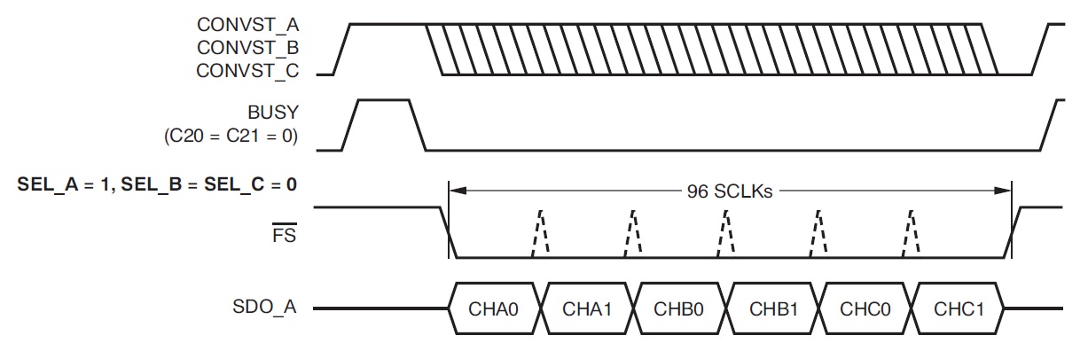
also in TDM mode. How do I set up the McASP for the operation especially to get a frame-sync that is low for 96 clocks?

Please see the following timing diagram that the ADC expects especially the frame-sync.

Also CONVST_A/CONVST_B/CONVST_C in the design is tied to GPIO5/EXT_INT5.

How can I generate the CONVST_A pulse as can be seen if I were to use DSP/BIOS?

Thanks,

Aditi.

  • You can set the number of TDM channels to be 6 + 1 16-bit channels, configure the McASP to use a frame-sync width of one word, and disable the very first channel.  Then you can invert the frame sync pulse to get the desired effect.  I'm assuming the data transfer will be continuous, so it's ok that the McASP will continue to transmit another frame after it's done with the last channel.


  • Gus,

    Yes, I am doing it as a 7 slot frame with the first slot inactivated.

    Have a quick question about the GPIOn lines of C6713.

    Can we setup the GPIO5 (say) to function as an external interrupt to another device?

    If so, how can we program the timing, say I want the the GPIO5 line to high whenever the

    McASP framesync line is high?

    Aditi.

  • Aditi Akula said:
    Can we setup the GPIO5 (say) to function as an external interrupt to another device?

    Yes

    Aditi Akula said:

    If so, how can we program the timing, say I want the the GPIO5 line to high whenever the McASP framesync line is high?

    Not sure what your specific requirements are (level, polarity, timing, etc.).  You could probably have to route the frame sync signal to a DSP GPIO.  You could then setup a GPIO interrupt and the in the ISR, toggle GPIO5.  However, why not just route the frame-sync signal to the other device's interrupt input? 

  • Gus,

    I am attaching the timing diagram that I want to meet.

    The CONVST_x signal in the diagram is tied to the GPIO5 signal in the design.

    I have to generate the CONVST_x signal as shown with respect to the FS signal from the McASP.

    I have generated the FS signal as we discussed before (using 7 TDM slots).

    Gus Martinez said:

     You could probably have to route the frame sync signal to a DSP GPIO.  You could then setup a GPIO interrupt and the in the ISR, toggle GPIO5.  However, why not just route the frame-sync signal to the other device's interrupt input?

    Should I route the frame-sync signal to a GPIO externally (like using some wires) or is there a way in software to do this?

    The design already has the GPIO going to CONVST_x of the ADC.

    Another question....

    When I use the DAT bus for receiving the data and have to receive 6 slots of data,

    where do I read the data from (as opposed to reading from the RBUFx register while using Peripheral config bus)?

    I understand that for DAT bus, the McASP register base address is 0x3c10 0000,

    so do the offsets still remain the same? Or how does the DAT bus work?


    Aditi.

  • Gus,

    Can you please reply.

    I am really waiting for your reply.

    Thanks,

    Aditi.


  • Aditi Akula said:
    The CONVST_x signal in the diagram is tied to the GPIO5 signal in the design.

    This is going to be a problem.  There is no good way to accurately control the timing of the GPIO signal wrt to the frame-sync output of the McASP.

    Aditi Akula said:

    I have to generate the CONVST_x signal as shown with respect to the FS signal from the McASP.

    I have generated the FS signal as we discussed before (using 7 TDM slots).

    I don't know if this is possible in your design, but blue wiring the frame-sync output of the McASP to the CONVST_x signal should work.  When the frame-sync signal goes high, it will force the ADS to start a new conversion.  Since the frame-sync will stay high for a total of 16-clocks, the timing tCONV should be met.  The BUSY pin should also be low long before the frame-sync signal goes low (i.e. assuming a 27MHz clock rate and a 16-bit slot size, FS high time = 37ns x 16 = 592 ns >> tD1 .  The timing t1 should also be easily met.  The only timing that will not be met is t3, since the frame-sync signal will go high immediately after the last clock thereby initiating a new conversion.  I am not sure if this will be a problem for the ADS device.  I recommend you start a new forum thread on the data converter forum.

    I don't see any other option to implement what you need.  It looks like the serial interface on the ADS device was designed for a SPI port.  Since the McASP does not support clock-stop mode, it is not well suited for this use case.  The McBSP would have been a much better option.  

    Aditi Akula said:

    When I use the DAT bus for receiving the data and have to receive 6 slots of data,

    where do I read the data from (as opposed to reading from the RBUFx register while using Peripheral config bus)?

    I understand that for DAT bus, the McASP register base address is 0x3c10 0000,

    so do the offsets still remain the same? Or how does the DAT bus work?

    You use a single address (0x3c10 0000), no offsets necessary.  You must write enough bytes to service all active serializers.  This is described in the "Transfers through the Data Port (DAT)" section of the McASP user guide.


  • Gus,

    I was able to blue wire the CONVST_x signals to frame-sync from the McASP.

    It looks like I am receiving some data.

    I am inputting a 1k sine wave but the clock to the ADC is very high like 500kHz

    and I can see some periodic samples coming into the DSP.

    I have more questions for the ADC on the Data converter forum.

    But have a quick question for you.

    Presently I have the McASP_RX ISR setup for receiving 6 channel data from the ADC.

    But I want to setup EDMA to take data from the McASP and store it in a buffer.

    Can I do this? If so, do I have to disable the ISR?

    I am kind of new to working with the EDMA/DMA.

    Thanks

    Aditi.

  • Aditi Akula said:

    Presently I have the McASP_RX ISR setup for receiving 6 channel data from the ADC.

    But I want to setup EDMA to take data from the McASP and store it in a buffer.

    Can I do this? If so, do I have to disable the ISR?

    You do not need the McASP ISR to process transmit/receive events since the EDMA will be moving the data.  However, I would still leave the McASP ISR since it can come in handy to process error conditions like under run or frame sync error.  You will need to create an EDMA ISR to process completion interrupts.  The EDMA will issue an interrupt when the data has been transferred to the destination memory.  Btw, you may want to think about implementing some type of ping-pong buffer scheme in which the DSP process data from one buffer, while the EDMA works on another buffer.  


  • Gus,

    In my application, I have to receive the Data from the McASP and send it over to external memory in the CE0 space.

    And this is a continuous process. So I am not planning to have a ping-pong buffer system.

    A quick question for you.

    In case I set up my EDMA in main(), do I need to setup the HWI in the TCF file for McASP_RX interrupt?

    Or just map the McASP_RX event to one of the EDMA channels, Setup EDMA and then let BIOS do the work?

    Also when you say by "create EDMA ISR", this will be a HWI_create in the TCF file, right?

    And in the ISR, I can just clear the interrupt bit in the EDMA Interrupt register, correct?


    Thanks,

    Aditi.

  • Aditi Akula said:

    In my application, I have to receive the Data from the McASP and send it over to external memory in the CE0 space.

    And this is a continuous process. So I am not planning to have a ping-pong buffer system.

    A ping-pong buffer scheme does not prevent you from processing continuous data.  DSP & EDMA continuously jump between ping and pong buffers.

    Aditi Akula said:

    In case I set up my EDMA in main(), do I need to setup the HWI in the TCF file for McASP_RX interrupt?

    Or just map the McASP_RX event to one of the EDMA channels, Setup EDMA and then let BIOS do the work?

    Also when you say by "create EDMA ISR", this will be a HWI_create in the TCF file, right?

    And in the ISR, I can just clear the interrupt bit in the EDMA Interrupt register, correct?

    Sorry, I am not fully understanding your BIOS questions.  I would advise you to look to the BIOS forum for more detailed help.  

    From a hardware setup perspective, you can definitely configure the CPU interrupt you have been using to now trigger on and EDMA interrupt.  However, it might be easier just to use a different interrupt.  The interrupt service routine will have clear the interrupt status from the EDMA itself.


  • Gus,

    I am a little confused on how the EDMA interrupt/ ISR will work.

    I have setup my McASP ISR and McASP Rx interrupts (used HWI 15).

    Also I have setup the EDMA with the necessary parameters (not yet used the ping-pong scheme).

    I wan to use the EDMAINT i.e. INT 8 for the EDMA interrupt.

    So do I setup HWI 8 for a EDMA ISR?

    If so, what should be the code in the EDMA ISR?

    Thanks,

    Aditi.

  • Aditi,

    I suggest you take a look at the "EDMAINT Servicing by the CPU" section in the C6000 DSP EDMA Controller Reference Guide. 

    EDMA Guide said:

    When a completion code is detected by the EDMACC, the EDMACC sets the

    appropriate bit in CIPR as per the transfer complete code specified. The CPU

    ISR should read CIPR and determine what, if any, events/channels have

    completed and perform the necessary operations. The ISR should clear the

    bit in CIPR upon servicing the interrupt; therefore, enabling recognition of

    further interrupts. Writing a 1 to the relevant bit clears the CIPR bits, writing a

    0 has no effect.

    By the time one interrupt is serviced, many others could have occurred causing

    additional bits to be set in CIPR. Each of these bits in CIPR are likely to need

    different types of service by the CPU. The ISR should check for all pending

    interrupts and continue until all the posted interrupts are serviced.

    Also, I recommend you take a look at the C6000 CSL API Guide.  If you download and install the source code you will see an EDMA example which sets up a ping-pong buffer and includes a sample EDMA ISR.  You will not need the IRQ functions because BIOS has its own interrupt setup mechanism, but the rest of the code should be useful to you.

    http://www.ti.com/litv/pdf/spru234c

    http://focus.ti.com/docs/toolsw/folders/print/sprc090.html


  • Gus,

    I have set up the EDMAINT and the EDMA ISR. THanks for your suggestion.

    The CE0 space is connected to a FPGA. And there is code in FPGA which takes the EMIF signals

    and acts as a asynchronous SRAM.

    This is how I have configured my EDMA port.

        /* Configure EDMA parameters */
        
          EDMA_configArgs(
              hEdmaAREVT,    
              EDMA_OPT_RMK(
                   EDMA_OPT_PRI_HIGH,
                   EDMA_OPT_ESIZE_16BIT,    /* Element size 32 bits */
                   EDMA_OPT_2DS_NO,
                   EDMA_OPT_SUM_NONE,
                   EDMA_OPT_2DD_NO,
                   EDMA_OPT_DUM_INC,
                   EDMA_OPT_TCINT_YES,      /* Enable Transfer Complete Interrupt    */
                   EDMA_OPT_TCC_OF(edmaChaAREVT),
                   EDMA_OPT_LINK_NO,       /* Enable linking to NULL table          */
                   EDMA_OPT_FS_YES
                   ),
               EDMA_SRC_RMK(MCASP_getRbufAddr(hMcasp)),      
               EDMA_CNT_OF(0x00000006),/* no. of elements   */
               EDMA_DST_RMK((int32_t)RxData),
               EDMA_IDX_OF(0x00000000),
               EDMA_RLD_OF(0x00060000)
         );     
                            
         /* Enable EDMA interrupts */
         EDMA_intDisable(edmaChaAREVT);
         EDMA_intClear(edmaChaAREVT);
         EDMA_intEnable(edmaChaAREVT);   

         /* enable EDMA channels */ 
         EDMA_enableChannel(hEdmaAREVT);

    The main aim is to transfer the 6 TDM data words from the McASP to the CE0 locations continuously.

    But in the CE0 space, I am able to receive only one word. while I want to receive all the 6 data words in contiguous

    address locations (see parameter INC in OPT register, DUM bit).

    Please guide.

    Aditi.