This thread has been locked.
If you have a related question, please click the "Ask a related question" button in the top right corner. The newly created question will be automatically linked to this question.
Hi TI team,
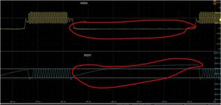
In out custom TDA4VM we are working with New DDR part from micron (MT53E1G32D2FW-046 AUT:B) in which we are seeing following waveform capture.
Normally during idle mode, the DQ should be from high to low. If the DDR controller configuration is incorrect do we see this issue. i have attached the DDR configuration spreadsheet we have used to generate the DDR configurations. Please have a look and let us know if any further changes required.
k3-j721e-ddr-evm-lp4-4266_13_09_22.zip
Regards,
Chaitanya
Hi TI team,
To summarize the problem statement above here.
1. Using DDR configuration spreadsheet tool and updated the values ( Timing information ) as per the new DDR datasheet
2. Generated the DDR configuration files and updated the firmware
3. with the generated configuration we are able to successfully flash and boot our custom board
4. above question is a basic question on DDR functionality behaviour, we see DQ should be high---> low in Idle mode but we see in DDR waveform capture we see low to high. wanted to validate the DDR configurations with TI team if any DDR controller configuration needs to updated or changed.
Regards,
Chiatanya
Hi,
My assumption is that DQ31 is not being actively terminated to ground during the time period circled in red from your scope image.
I am not aware of any reason why you would need to deviate from the settings provided in the latest tool (v0.9.1): https://www.ti.com/lit/pdf/spracu8
Regards,
Kevin
Hi Kevin,
Thanks for the feedback.
We have not modified any settings given in the spreadsheet except '' DDR Density( Per channel)'' because our new DDR part is a dual die 16Gb per channel.
Do you think the termination settings used in the spreadsheet shall need to be modified? since Data signals are not actively terminating to ground? Please advise.
Regards,
Chaitanya
When termination is enabled, the LPDDR4 memory automatically turns it on and off depending on whether a WRITE is actively occurring or not. You have circled a region where it does not appear a write is occurring, and thus my assumption is that the signal is not being terminated to ground. I do not think there are any register settings that can be modified to change this behavior.
Kevin