This thread has been locked.

If you have a related question, please click the "Ask a related question" button in the top right corner. The newly created question will be automatically linked to this question.

TMS320C6746: Interfacing MMC/SD controller to eMMC Memory

Part Number: TMS320C6746

Hello TI,

Please check the image attachment for MMC/SD to eMMC
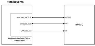
As we are planning to interface MMC/SD controller of TMS320C6746 to a standard eMMC memory.

Can you please comment on the correctness of above statement or if there are any other ways to implement this??

And also let us confirm whether we can do POWER ON BOOT from eMMC memory.??

Thanks,

Rajesh..

  • The device supports booting from an eMMC device from the MMC/SD0 port. The details are described in an Application Report titled Using the TMS320C6748/C6746/C6742 Bootloader.

    I would recommend placing a series termination resistor in the CLK signal path with very short signal trace between this resistor and the TMS320C6746 MMCSD0_CLK pin. Installing a 22 ohms resistor would be a good starting value, but it may be necessary to change the value to optimize signal integrity of the clock signal.

    Regards,
    Paul

  • Hello Paul,

    Thanks for your reply.

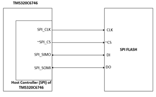
    To make the Interface simple we are planning to interface an SPI controller to the standard SPI flash.

    Please check the image attachment for your reference.

    Whether we can do AUTO BOOT from the SPI flash while powering on without any triggering?
    Whether the DSP can act as a MASTER for generating the required clock signal to SPI flash in doing AUTO BOOT?

    Could you please comment on the correctness of above statements?? If Yes we can drop eMMC booting.

    Thanks,
    Rajesh..

  • It has been several years since this device was released into the market. The original designers are no longer available to answer questions, so I'm simply reading the Application Report mentioned in my previous post.  Based on the information provided in the Application report you should be able to select one of four possible BOOT MODE options (SPI0 EEPROM, SPI1 EEPROM, SPI0 Flash, or SPI1 Flash), where the device operates as a SPI master.  I would expect the device to automatically begin sourcing the appropriate signals to the attached SPI device to begin reading data if you select one of these modes.

    I recommend including a series termination resistor on the appropriate SPI clock signal, similar to what was mentioned before for the MMCSD clock signal.

    Regards,
    Paul

  • Hello Paul,

    Thanks for your reply.

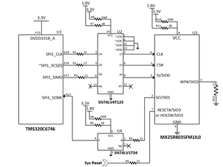
    Please find the image attachment for your reference..

    We are planning to use this serial flash from Macronix.. Part Number:MX25R8035FM1IL0

    As the information provided in the application report the TI DSP must have '24-bit addressing' and '03h' as a read command instruction and we have selected the part mentioned above..

    So, Could you please confirm on the part that we have selected? And also let us know whether there are any other concerns from your side regarding the interfacing of this Macronix part with the TI DSP??

    Thanks,

    Rajesh..

  • I cannot officially confirm this device will work because we do not have a hardware platform with this combination of components. However, it appears the Macronix device meets the expectations defined in the application report. I also confirmed the TI 74LV4T125 is 3.3V tolerant when operating at 1.8V and the TI 74LV1T34 VIH min is compatible with a 1.8V signal applied to its input when operating at 3.3V.

    The TMS320C6746 datasheet defines timing for various combinations of Polarity and Phase. I seem to recall the application report defines which timing mode is being used for boot. You should confirm this timing mode is compatible with the Macronix device timing. I recommend doing a timing analysis to verify there is enough setup/hold margins for each device when considering the respective min/max output delays of the attached device after including PCB trace delays.

    Regards,
    Paul