This thread has been locked.

If you have a related question, please click the "Ask a related question" button in the top right corner. The newly created question will be automatically linked to this question.

TDA4VM: LDC de-distortion edge anomaly problem

Part Number: TDA4VM

Hello, about the de-distortion function of the TI LDC module, I encountered some problems in the actual autopilot project (L2++), and I hope to answer:
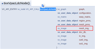
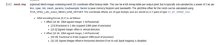
1. Use Ldc to load the de-distortion table. After de-distortion, the image effect is a sawtooth image. After changing the ldc parameters, the block becomes smaller from 64×64 to 8×8, but the time-consuming is changed from 3ms to 30ms. This time-consuming can not be used in the actual project, is this normal?

2. Using the distortion table generated by the DCC tool recommended by TI FAE, the image effect is:

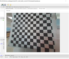
can see the image with virtual edges, is there any solution?
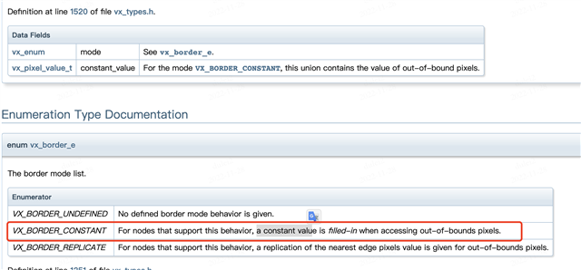
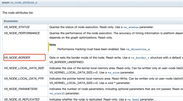
3. Our requirement here is whether the LDC can set the edge filling mode. At present, it seems that the status quo is that when encountering values outside the image, it will fill the most edge pixels, resulting in abnormal image edges (jaggies or blurring).
Looking forward to reply, thank you very much

  • 1. 

    It looks like your mesh LUT or your geometric transform goes out of the input image borders.
    There may be some issues with your mesh LUT around the boarders otherwise the green pixels shall never happen.

    2 and 3

    Yes, repeating the edge pixel values is the H/W behavior it goes out of the input image boundary.
    The only way to get some fixed pixel values is to pre-pad your LDC input images with a border (e.g., a few black pixels on each sides).

  • Dear Gang,

         Here is their DCC file, sorry I forget to upload it.

    hozon.7z  

    BR

    Sikai

  • we have checked map_x and map_y , if it's value out of the input image borders ,we set value 1;  we test it by opencv cv::remap(image, test_undistort, map_x_read, map_y_read, cv::INTER_LINEAR); and it looks ok.  is there some different ?

  • and the block size from 64×64 to 8×8, the green pixels  get small ,     
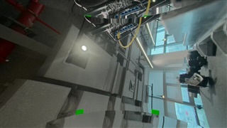
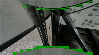
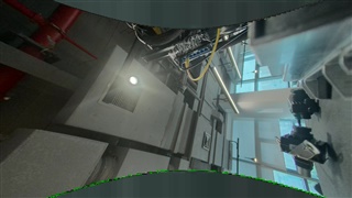
the block size changes the green pixels changes not pixels out of the input image borders cause

  • Hi,

    The mesh LUT in "hozon.7z" is different from your above picture and it does not show similar problems.
    Please upload the right project with the same LUT.

    Going out of image border is not a big problem and LDC H/W can clip back to image border (repeating the same border pixels).
    "hozon.7z" has this problem, but it does not give any green pixels.

    The issue you showed above is due to some discontinuity issue in mesh LUT which results in very large input pixel block size and LDC runs out of internal memory.
    Reducing the block size will help in this case as you noticed.
    We will need to take a look at your tuning tool project with your mesh LUT.

  • Hi,

    The mesh LUT in "hozon.7z" is generate by matlab. it is different above picture.  we don't want repeating the same border pixels, so FAE suggest us use DCC Tool to do this, but it still has repeating the same border pixels. how to deal with?

    the green pixels is we use opencv generate map_x map_y,and get offset from the maps, fill the offset in mesh LUT.

    Reducing the block size will cause time-consuming is changed from 3ms to 30ms ,and  still have some green pixels.

  • the mesh LUT binary 

    文件名:center_camera_fov120_meshtable.7z
    文件链接:deliverycenter.sensetime.com/.../c794a02d-b498-4f6a-99ce-9529c8c97e50
    提取码:LnWnGJcZ

  • Hi Dulei,

    Could you please share your tuning tool project (similar to "hozon.7z") with your new LUT?

    What is format of this new binary file?

  • Hi Gang Hua,

    the new LUT have no tuning tool project,  because the new LUT is come from :

    1.cv::initUndistortRectifyMap generate map_x, map_y;

    2. fill map_x, map_y value to  1,while it's value overflow intput image border;

    2. get map_x_offset ,  map_y_offset from map_x, map_y;

    3. fill the map_x_offset ,  map_y_offset to LUT , 

    the tuning tool project generate LUT is different while sensor change. we can't generate a LUT for every sensor,  it's hard for our project, and the tuning tool  is run on windows platform, but we want generate LUT on the TDA4VM platform when sensor intrinsic changes.  


    format of this new binary file is  mesh LUT  which can load and run by the ldc node.  it's same with "ldc_lut_1920x1080.h" content

  •  we reference this  to fill the map_x_offset ,  map_y_offset to mesh LUT and  save to binary file format

  • we tried set VxNode  VX_NODE_BORDER  reference from 

    but it didn't take effect, is there suppourt openvx standard?

  • Hi Gang Hua,

    we convert mesh LUT binary to ldc_lut_1920x1080.hpp 

    文件名:ldc_lut_1920x1080.hpp
    文件链接:deliverycenter.sensetime.com/.../4baae820-fd93-4fad-8f7f-418208cd6faa
    提取码:052s2LjF

  • Hi Dulei,

    Thanks for the explanation!
    I would recommend using the tuning tool to check your mapping and find out the proper LDC parameters.

    The green output pixels are typically caused by LDC running out of internal memory and/or discontinuity in the LUT.
    Tuning tool allows both checking those errors and finding the proper LDC parameters to avoid running out of internal memory.

    Your green block issue is from your "ldc_lut_1920x1080.hpp" where you clipped your coordinates in a wrong way.

    2. fill map_x, map_y value to  1,while it's value overflow intput image border;

    You clip to the image corner regardless where it goes out of the image border.
    It will cause bad entries in LUT and let LDC run out of memory.

    You shall clip to nearest pixel on the border.
    In other words, your x/y values shall be continuous after clipping.

  • In other words, your x/y values shall be continuous after clipping.

    I don't understand why we must keep x/y of map  continuous ?  

    The x/y value represents the offset ?

  • HI Gang Hua,

    Your green block issue is from your "ldc_lut_1920x1080.hpp" where you clipped your coordinates in a wrong way.

    2. fill map_x, map_y value to  1,while it's value overflow intput image border;

    You clip to the image corner regardless where it goes out of the image border.

    why it is a wrong way ?

    The map_x/map_y saves Absolute coordinates,  it means get current pixel value from image (1,1),  when it goes out of the image border .

    The ldc_lut saves map_x_offset/map_y_offset. 

    we get map_x_offset from map_x detail:

    for (auto row = 0; row < img_size.height; row++) {
    for (auto col = 0; col < img_size.width; col++) {
    float32_t xs = map_x.at<float>(row, col);
    float32_t ys = map_y.at<float>(row, col);
    float32_t x_offset = xs - static_cast<float>(col);
    float32_t y_offset = ys - static_cast<float>(row);
    map_x_offset.at<float>(row, col) = x_offset;
    map_y_offset.at<float>(row, col) = y_offset;
    }
    }
  • we tried fill map_x_offset, map_y_offset value (0,0), when it goes out of the image border.

    we got output:

    why Inside the border has green pixels ?

    why the repeat pixels Inside the border?

  • (1)  >> why Inside the border has green pixels?

    This is caused by your clipping to (0,0) resulting in large jumps (discontinuity) in the mesh LUT.
    LDC is a H/W IP which as limited internal memory size.

    Large jumps as in the below example from (97, 0) to (0, 0) in the mesh LUT causes LDC running out of internal memory.
    You should keep it as continuous as in the C row while preparing the mesh LUT.

    A: (99, 2), (98, 1), (97, 0), (96, -1), (95, -2)
    B: (99, 2), (98, 1), (97, 0), (0, 0), (0, 0)
    C: (99, 2), (98, 1), (97, 0), (96, 0), (95, 0)

    (2) >> why the repeat pixels Inside the border?

    This is H/W behavior.
    When LDC is asked to output a pixel out of the image border, it will use the nearest pixels on the border.

  • HI Gang Hua,

    Thanks for the explanation!

    It is difficult to meet our requirements in this way.

    Our appeal is to support setting default values out of input image border.

  • >> setting default values out of input image border.

    Unfortunately, that is not supported by H/W directly even although I also prefer to have that feature.
    The only workaround is to pad the input images with those default pixels, e.g., 2 rows on top and 2 rows on bottom for your example image above.
    When getting out of the image border, H/W repeats the padded pixels.

    On the green artifact issue, you will have to clip as in row (C) rather than row (B) above.
    Otherwise, LDC will run out of memory.

  • Hi, Excuse me, we have some LDC problems here. We have created a new problem tracking link. As you are an expert in this field, can you help us take a look。e2e.ti.com/.../tda4vm-distorted-image-of-ldc-is-different-from-that-of-opencv

  • sure.

    Do you have any more issues with this thread?