This thread has been locked.

If you have a related question, please click the "Ask a related question" button in the top right corner. The newly created question will be automatically linked to this question.

TDA4VM: Hardware Considerations while selecting the Boot NOR Flash

Part Number: TDA4VM

Hi,

I would like to know list of technical specifications consider for selecting the NOR Boot Flash for TDAV4MID SOC.

Supply voltage=3.3V

Page Program size-128B

Sector size -4KB/8KB/64KB

Uniform Boot sector is preferred or not

Top or Bottom Boot.

Anything else??

Thanks-Arumugam

  • Arumugam

    I'm assuming you asked a related question to "https://e2e.ti.com/support/processors-group/processors/f/processors-forum/946418/faq-tda4vm-is-there-a-guide-to-choosing-the-right-ospi-flash-parts-that-are-supported-on-jacinto-7" 

    (i.e. you did review that FAQ which has the guide for choosing the correct flash part)

    There is an additional app note that might also be helpful: 

     https://www.ti.com/lit/an/spracy5/spracy5.pdf?ts=1673563550932&ref_url=https%253A%252F%252Fwww.google.com%252F 

    John

  • Hi,

    We decided to go with 2Gb (4 die part) from Micron and the part# is MT35XU02GCBA1G12-0AUT. I have the below questions.

    • From our understanding, there will not be any timing information, other Electrical characteristics and software requirements changes, if Single die /quad die devices operating in SDR mode.
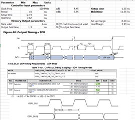
    • As per our timing analysis, the maximum frequency we can achieve as 100MHz for read and 125MHz for write to meet the set up and hold margin.

    Read Command

    • .

    Write Command

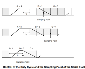
    • Does TDA4VM has the below feature for SPI. it will help to improve the set-up requirement.
  • The OSPI PHY SDR Mode timings will be improved in a future revision of the datasheet. Below are the values that will updated. Please evaluate your system timings using these values, and let me know if you have any questions.

    Table. OSPI Timing Requirements – PHY SDR Mode

    NO.


    MODE

    MIN

    MAX

    UNIT

    O19

    tsu(D-CLK)

    Setup time, OSPI0_D[7:0] valid before active OSPI0_CLK edge

    1.8V, SDR with Internal PHY Loopback

    4.8


    ns


    3.3V, SDR with Internal PHY Loopback

    5.19


    ns

    O20

    th(CLK-D)

    Hold time, OSPI0_D[7:0] valid after active OSPI0_CLK edge

    1.8V, SDR with Internal PHY Loopback

    -0.5


    ns


    3.3V, SDR with Internal PHY Loopback

    -0.5


    ns

    O21

    tsu(D-LBCLK)

    Setup time, OSPI0_D[7:0] valid before active OSPI0_DQS edge

    1.8V, SDR with External Board Loopback

    0.6


    ns


    3.3V, SDR with External Board Loopback

    0.9


    ns

    O22

    th(LBCLK-D)

    Hold time, OSPI0_D[7:0] valid after active OSPI0_DQS edge

    1.8V, SDR with External Board Loopback

    1.7


    ns


    3.3V, SDR with External Board Loopback

    2.0


    ns