

Hello,
Is there any additional information that you can provide in order to more easily configure Sitara GPMC registers?

This thread has been locked.
If you have a related question, please click the "Ask a related question" button in the top right corner. The newly created question will be automatically linked to this question.
Hello,
Is there any additional information that you can provide in order to more easily configure Sitara GPMC registers?
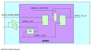
The figure below gives a simplified overview of the GPMC datapath. In synchronous mode, data from the flash are first captured on a GPMC_CLK rising edge, and then on a GPMC_FCLK rising edge. The second capture is enabled by logic that takes RDACCESSTIME, WAITMONITORING and GPMCFCLKDIVIDER into account.
NOTE: When the GPMC is configured for synchronous mode, the GPMC_CLK signal (which is an output) must also be set as an input (CONTROL.CONTROL_PADCONF_GPMC_NCS7[24] INPUTENABLE1 = 1). GPMC_CLK is looped back through the output and input buffers of the corresponding GPMC_CLK pad at the device boundary. The looped-back clock is used to synchronize the sampling of the memory signals.
The important point is that the second capture will occur at cycle number: · RDACCESSTIME+1 if GPMCFCLKDIVIDER is 0 (GPMC_CLK = GPMC_FCLK) , · RDACCESSTIME+2 if GPMCFCLKDIVIDER is greater than 0 (GPMC_CLK = GPMC_FCLK divided by 2, 3 or 4)
As the maximum GPMC_CLK speed is 100MHz, the logical path between the first sampling flop (on GPMC_CLK) and the second one (on GPMC_FCLK) was characterized to be 10ns long.
Rule 1. PAGEBURSTACCESSTIME must be a multiple of GPMCFCLKDIVIDER+1.
For synchronous accesses, your access time per burst must take into consideration the clock divider for the GPMC module.
For example, if your L3 Clock is 166MHz, you have to reduce the GPMC_CLK by setting GPMCFCLKDIVIDER=1 (ie, divide by 2).
GPMC_FCLK = 166MHz GPMC_CLK = 83MHz
Thus PAGEBURSTACCESSTIME must be a multiple of 2 (which implies a minimum of 2 as well). Thus, if you set PAGEBURSTACCESSTIME to 4, your burst will be 2 GPMC_CLK cycles long.
Rule 2. (RDCYCLETIME – CLKACTIVATIONTIME) must be a multiple of GPMCFCLKDIVIDER+1.
Similar to Rule 1, this also ensures the synchronous access ends with a rising edge on both GPMC_CLK and GPMC_FCLK.
Rule 3. (RDACCESSTIME – CLKACTIVATIONTIME) modulus (GPMCFCLKDIVIDER + 1) must be different from GPMCFCLKDIVIDER
This is a consequence of the internal sampling scheme in OMAP3 (see block diagram above). Violating this rule will not result in broken functionality, but rather in a limitation in the maximum GPMC_CLK frequency.
Figure 1 illustrates the sampling timing when Rule 3 is followed. The blue traces show the case where (RDACCESSTIME - CLKACTIVATIONTIME)%2 = 0, the red traces show the case when (RDACCESSTIME - CLKACTIVATIONTIME)%2 = 1.
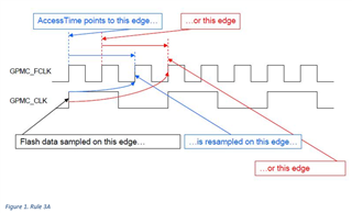
Figure 2 shows an example where Rule 3 is violated. The data is re-sampled only one clock cycle after the initial sample.
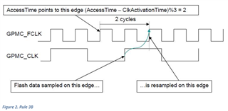
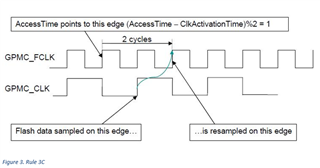
Figure 3 shows an example where Rule 3 is violated. Again, the data is re-sampled only one clock cycle after the initial sample.
Rule 4. If GPMCFCLKDIVIDER is greater than 0, RDCYCLETIME must be greater or equal to RDACCESSTIME+2. If GPMCFCLKDIVIDER is 0, RDCYCLETIME must be greater or equal to RDACCESSTIME+1.
This is also a consequence of the sampling scheme described above. If Rule 4 is not obeyed, then the end of the access (determined by RDCYCLETIME) will occur before the last data is sampled on the second flop (at RDACCESSTIME+1 or RDACCESTIME+2 depending on GPMCFCLKDIVIDER). This will cause undefined behavior of the GPMC state machine.
Rule 5. If GPMCFCLKDIVIDER is greater than 0 and WAITREADMONITORING is enabled, CSRDOFFTIME must be greater or equal to RDACCESSTIME+2. If GPMCFCLKDIVIDER is 0 and WAITREADMONITORING is enabled, CSRDOFFTIME must be greater than or equal to RDACCESSTIME+1
This rule is another consequence of the sampling scheme described above. In synchronous mode of the GPMC, when wait monitoring is enabled, the internal GPMC state machine looks for wait assertion/deassertion. The state machine is designed so that in this case, one extra clock cycle is needed. If CSRDOFFTIME does not take this extra clock cycle into account, the GPMC state machine will go to an undefined state.
Rule 6. If GPMCFCLKDIVIDER is greater than 0 and WAITREADMONITORING is enabled, OEOFFTIME must be greater or equal to RDACCESSTIME+2. If GPMCFCLKDIVIDER is 0 and WAITREADMONITORING is enabled, OEOFFTIME must be greater than or equal to RDACCESSTIME+1.
The reasoning for this is the same as Rule 5, but it applies to the OE signal.
Rule 7. Regardless of WAITREADMONITORING and GPMCFCLKDIVIDER, OEOFFTIME and CSRDOFFTIME must be greater than or equal to RDACCESSTIME+1.
This rule is a consequence of the GPMC state machine implementation: for synchronous burst access, the GPMC state machine takes one cycle after AccessTime to freeze the counters controlling the CsRdOffTime and OeOffTime.
Take the example if the software is doing a two word burst, and we have RDACCESSTIME = OEOFFTIME. At RDACCESSTIME+1, the GPMC state machine adds PAGEBURSTACCESSTIME to OEOFFTIME, But it is already too late to deassert OE at the end of this cycle. This causes OE to be deasserted on cycle later. The same is true for CS and for longer burst access.
