This thread has been locked.

If you have a related question, please click the "Ask a related question" button in the top right corner. The newly created question will be automatically linked to this question.

AM62P5-Q1: P1: HW: Q131-1: Pull-up pull-downs on eMMC data lines

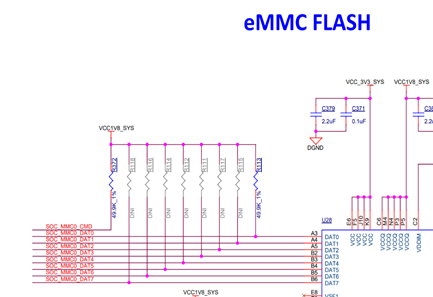
On the AM62A EVM, only CMD and Dat0 have pull-up.  What are the reasons that pull-up resisters on DAT[7:1] pins are not installed?

  • Reassigning to our expert to address.

    Thanks,

    Chris

  • Because the eMMC standard requires all eMMC devices to turn on internal resistors for each of the DAT[7:1] pins until the device is configured to operate in 4-bit mode or 8-bit mode.  When the bus width changes any unused signals remain pulled high by internal pulls, but the others are turned off and the host is expected to turn on its internal pulls to hold the bus in a valid logic state while not driven.

    You didn't ask about CLK, but there should be an external pull-down resistor installed on this signal to hold it low until the host is configured to drive the signal. This is required to prevent the eMMC clock input from floating until software initializes the respective pin multiplexing and clock source.

    Regards,
    Paul

  • The question is about during reset or after reset before the internal PU/PD are effective.

  • The internal pulls on most AM62Px pins will be turned off until software initializes the respective PADCONFIG register. The state of each pin is defined in the datasheet.

    The customer must ensure their system design doesn't allow input pins of attached devices to float until software turns on our internal pulls or drives a valid logic state on the signals.

    In the eMMC use case, the eMMC device will perform this task by applying its internal pull-ups on the DAT[7:1] signals. External pull-up resistors will be needed for the DAT0 and CMD signals. An external pull-down will be required for the CLK signal.

    Regards,
    Paul