This thread has been locked.

If you have a related question, please click the "Ask a related question" button in the top right corner. The newly created question will be automatically linked to this question.

Are all pins on a D-sub needed?

Anonymous
Anonymous

Hi,


I would like to ask a question on VGA D-sub connection.


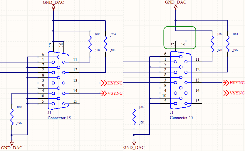
Properly, the 16 and 17 pins should be connected to GND_DAC ground. However, due to the mismatch between the D-Sub header I bought and my board, I was forced to cut pin 16 and 17 off from the D-Sub connector before soldering it.


Afterwards in testing, I got no video display when connected to a monitor, and I can be sure that the software routine and device configuration (VPBE, etc.) are all correct.


So is it possibly due to the two missing pins 16 and 17? They are originally supposed to GND_DAC ground, why would removing them probably matter or not?

  • Hello Zheng,

    Yes, the shield should be connected to ground to maintain proper signal integrity.

    A standard VGA connector should also include a DDC interface (pins 9, 12 and 15) to access the EDID ROM in the monitor.

    Please provide the TI device you're trying to interface to so that I can forward your questions to the proper forum.

    Regards,

    Jim

  • Anonymous
    0 Anonymous in reply to James Nave

    Jim,

    James Nave said:

    A standard VGA connector should also include a DDC interface (pins 9, 12 and 15) to access the EDID ROM in the monitor.

    Question 1:

    http://en.wikipedia.org/wiki/Display_Data_Channel said:

    The Display Data Channel or DDC is a collection of digital communication protocols between a computer display and a graphics adapter that enables the display to communicate its supported display modes to the adapter and to enable the computer host to adjust monitor parameters, such as brightness and contrast.

    I am using a DM6437 chip and uses its VPBE (Video Processing Back End) to generate displaying signal. It seems to me unlikely that VPBE is capable of doing the bilateral communication with monitor, but is only able to send out signal unilaterally.

    Are you familiar with VPBE? Does it support DDC?


    Question 2:

    I have been using a board with pin

    1. 9 & 15 unconnected
    2. 12 connected to ground via a 10K resistor

    as shown in the picture above. Does this mean at least it is NOT designed to be DDC compatible?


    Zheng


  • Hello Zheng,

    Your VGA connector does not support the VESA DDC interface.

    The DDC interface can be implemented using a standard I2C interface on the DM6437.

    I'm going to forward your questions to the DM6437 forum.

    Regards,

    Jim

  • Anonymous
    0 Anonymous in reply to James Nave

    Jim,

    Thanks for the answer.


    Zheng