This thread has been locked.

If you have a related question, please click the "Ask a related question" button in the top right corner. The newly created question will be automatically linked to this question.

TDA4VM: [Urgent Issue] In some cases, the low or high level time of GPIO waveform is longer than the time set by the software.

Part Number: TDA4VM

Hi, TI expert
Background of the question:
1) Our radar uses GPIO+DMA scheme, which runs in mcu3-0. The radar will always be in working state after starting up, and send the collected data to A72 through IPC;
2) Our parking application and algorithm runs in A72. In parking mode, it continuously processes radar data. In non-parking mode, data is received but not processed.

Question:
In non-parking mode, the radar works normally. In parking mode, the following problems may exist:
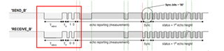
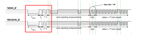
When mcu3-0 uses GPIO to generate command waveform, the actual measured low level time or high level time of hardware waveform is longer than that set by the software. For example, the low level time set by the software is 200us, but the actual measured waveform time is 215us.
This would cause the radar to be unable to parse the command waveform, thus not sending radar data to the MCU3-0.

The above questions are only available in parking mode. We would like to know:
1. Will the high load of A72 affect the operation of MCU3-0?
2. Will A72 and MCU preempt software resources or hardware resources?

The above problem is urgent, please help to analyze, thank you ~!

  • Hi TI expert
    The problem is urgent. Do you have any suggestions for our reference?

  • Hi,

    Yes, there is a possibility that higher load mainly DDR can cause potentially delay transfer slightly. This mechanism uses DMA to read and/or write GTC timestamp using DMA and read/write to the DDR.

    Can you try putting the buffer from where you are reading/writing to some internal memory? May be MSMC/OCMC or TCM memory and see if you can get better timestamp?

    Regards,

    Brijesh

  • Hi, Brijesh
    1. Yes, there is a possibility that higher load mainly DDR can cause potentially delay transfer slightly. This mechanism uses DMA to read and/or write GTC timestamp using DMA and read/write to the DDR.
    >>>>>
    I think I may not have described the problem clearly, specifically as follows:
    First of all, the operation steps of our program are: 1) set GPIO1 on the tda4 side to send a command waveform to the uss side; 2) start dma; 3) The uss side transmits waveform to the tda4 side through GPIO2 and triggers dma to record the time stamp.
    Our problem is at step 1), where dma is not involved.
    When the command waveform is generated on the tda4 side, the actual measured low level time or high level time of the hardware waveform is longer than that set by the software. For example, if the low level time set by the software is 200us, the actual measured waveform time is 215us.

    2.
    Can you try putting the buffer from where you are reading/writing to some internal memory? May be MSMC/OCMC or TCM memory and see if you can get better timestamp?
    >>>> Can you provide a specific step and method, or demo? Our other question should be related to this.

  • Hi, Brijesh
    Do you have any information for feedback?

  • Hi jia wentao,

    Sorry for the late reply, can you please share some more information on step1?

    - What is the command you are sending on GPIO1? 

    - how do you set the 200us low level time? 

    - are you using any other sw on the same core, which can block gpio processing? can you disable interrupts while writing to gpio registers? 

    Regards,

    Brijesh

  • Hi, Brijesh
    First of all, thank you for your reply and help.
    - What is the command you are sending on GPIO1?
    -->>>> Send the following ultrasonic command waveform in the red box.


    - how do you set the 200us low level time?
    -->>>> Use the custom delay function to achieve the delay, as follows:
    #define SNR_GET_GTC_VALUE64 (*(volatile uint64_t*)(0xA90008U))
    #define SNR_WAIT_US_VER2(x) \
    { \
    uint64_t cur_time = SNR_GET_GTC_VALUE64/200; \
    while((SNR_GET_GTC_VALUE64/200) - cur_time < x) ; \
    }

    SNR_WAIT_US_VER2(200);

    - are you using any other sw on the same core, which can block gpio processing? can you disable interrupts while writing to gpio registers?
    -->>>> Currently in MCU3-0, only Radar upa1, upa2 and apa three threads. The priority of the three threads has been set to the highest. Locks and disable interrupts are used when working with GPIO, as follows:

    MutexP_lock(emitMutex, MutexP_WAIT_FOREVER);
    key=HwiP_disable();
    ... ...
    GPIOPinWrite_v0(CSL_GPIO0_BASE , pinnum, GPIO_PIN_LOW);
    SNR_WAIT_US_VER2(200);
    ... ...
    HwiP_restore(key);
    MutexP_unlock(emitMutex);

  • Hi jia wentao,

    Is this part of the code cached? Also can you please confirm that both setting GPIO level low and high are done when Hwi is disabled? What i am suspecting is the loop in SNR_WAIT_US_VER2 itself slightly longer time and so GPIO toggle got bit delayed. 

    Regards,

    Brijesh

  • Hi, Brijesh
    Is this part of the code cached?
    -->> How do you mean code cache? I don't think we have a code cache. Will caching this part of the code solve the problem?

    Also can you please confirm that both setting GPIO level low and high are done when Hwi is disabled?
    -->> After hwi is disabled, command waveforms that change high and low levels are continuously sent according to the waveforms in the red box below.

    Also, there is the question of whether interrupt responses from other programs are paused or aborted if the HwiP_disable() function is used. If it is paused, will it be resumed?

    What i am suspecting is the loop in SNR_WAIT_US_VER2 itself slightly longer time and so GPIO toggle got bit delayed.
    -->> Are there other precise and us delay functions available for rtos? Or is there a way to make SNR_WAIT_US_VER2() work more accurately?

  • Hi,

    -->> How do you mean code cache? I don't think we have a code cache. Will caching this part of the code solve the problem?

    Please check this in your MPU configuration for the core where you are running this code. See if the code section is cached. Yes if it is not cached, it can affect the performance.

    -->> After hwi is disabled, command waveforms that change high and low levels are continuously sent according to the waveforms in the red box below.

    ok

    -->> Are there other precise and us delay functions available for rtos? Or is there a way to make SNR_WAIT_US_VER2() work more accurately?

    Ideally should use interrupt to get the time.. But lets first check if the code is cached. 

    Regards,

    Brijesh

  • Hi, Brijesh
    Please check this in your MPU configuration for the core where you are running this code. See if the code section is cached. Yes if it is not cached, it can affect the performance.
    >>>>
    1) Do you mean the "tda4 / rtos - SDK/vision_apps/platform/j721e/rtos/McU3_0 / j721e_mpu_cfg c" file configuration? We have not made any changes to this file.
    2)If not, please explain in detail how to check if code is cached. We have not done code caching before, thank you for your help.

  • Hi,

    In this file, entire 2GB memory from 0x80000000 is cached, so If your code is included in this 2GB memory, it is already cached.. 

    This API GPIOPinWrite_v0 is implemented in  csl/csl_gpioAux.h as inline function, and it looks like it is doing some division operation, it can further delay. Can you please try writing to the register directly in the code? 

    Regards,

    Brijesh

  • Hi, Brijesh
    Sorry for the late reply.
    In this file, entire 2GB memory from 0x80000000 is cached, so If your code is included in this 2GB memory, it is already cached..
    ==>> If so, our mcu3-0 code should be cached. Because:
    In the "tda4 / rtos - SDK/vision_apps/platform/j721e/rtos/McU3_0 / j721e_linker_freertos. CMD" file has the following Settings
    .text : {} palign(8) > DDR_MCU3_0

    In the "tda4 / rtos - SDK/vision_apps/platform/j721e/rtos/McU3_0 / linker_mem_map. CMD" file has the following Settings
    /* DDR for MCU3_0 for code/data [ size 15.00 MB ] */
    DDR_MCU3_0 ( RWIX ) : ORIGIN = 0xA6100400 , LENGTH = 0x00EFFC00

    So the code snippet of mcu3-0 (0xA6100400) is already contained in 2 gigabytes of memory starting at 0x80000000, right?

    This API GPIOPinWrite_v0 is implemented in csl/csl_gpioAux.h as inline function, and it looks like it is doing some division operation, it can further delay. Can you please try writing to the register directly in the code?
    ==>> It's been tried before, but it hasn't been very effective.

    In addition, I have a few questions:
    1) How long does it take from setting the gpio register to the actual hardware output high or low level?
    2) Can the waveform produced by tda4 gpio achieve the accuracy of microseconds? Make sure that our hardware solution is right.

  • Hi Jia wentao,

    ok, it seems it is cached.

    Before checking HW level, can you check exactly at what time do you change GPIO level? You could take diff of GTC counter value and really confirm if it is exactly 200us. 


    Regards,

    Brijesh

  • Hi, Brijesh
    Before checking HW level, can you check exactly at what time do you change GPIO level?
    ===>>> The gpio level will be changed when the command waveform is sent, just like the previous waveform. Is that what you asked?
    You could take diff of GTC counter value and really confirm if it is exactly 200us.
    ===>>> I'll confirm and get back to you later.

  • Thanks, lets get the GTC values and confirm that the delay is really around 200us.

    Regards,

    Brijesh

  • Hi, Brijesh
    Sorry to keep you waiting for a long time, I went to do some tests, the test code is as follows:


    global_time1 = appLogGetGlobalTimeInUsec();
    SNR_WAIT_US_VER2(200);
    global_time2 = appLogGetGlobalTimeInUsec();
    global_diff = global_time2 - global_time1;
    printf("200set_delay %d real_delay %lld\n",delay,global_diff);

    global_time1 = appLogGetGlobalTimeInUsec();
    SNR_WAIT_US_VER2(50);
    global_time2 = appLogGetGlobalTimeInUsec();
    global_diff = global_time2 - global_time1;
    printf("50set_delay %d real_delay %lld\n",delay,global_diff);

    global_time1 = appLogGetGlobalTimeInUsec();
    SNR_WAIT_US_VER2(30);
    global_time2 = appLogGetGlobalTimeInUsec();
    global_diff = global_time2 - global_time1;

    printf("30set_delay %d real_delay %lld\n",delay,global_diff);


    The test results show that most of the delay function is accurate, but sometimes it is not accurate.
    For example:(More than 60,000 tests were captured.)
    1) When setting the 200us delay, sometimes the actual delay time was only 11us(only once), and sometimes 219us.
    2) When the delay is set to 50us, the actual delay time is sometimes measured to be 60us.
    3)When the delay is set to 30us, the actual delay time is sometimes measured to be 48us.

  • Hi,

    This is what i was worried about. If the delay itself is not correct GPIO toggle will also not be correct.. 

    Can you please move this part of the code to some internal memory like TCM? Lets see if this helps. 

    Regards,

    Brijesh

  • Hi, Brijesh

    Thank you for your guidance. I really agree with your suggestion, but before verification, you need to help confirm the following problems:
    1.
    tda4/rtos-sdk/vision_apps/platform/j721e/rtos/mcu3_0/j721e_linker_freertos.cmd
    .text : {} palign(8) > DDR_MCU3_0

    tda4/rtos-sdk/vision_apps/platform/j721e/rtos/mcu3_0/linker.cmd
    .text : {} palign(8) > DDR_MCU3_0

    tda4/rtos-sdk/vision_apps/platform/j721e/rtos/mcu3_0/linker_mem_map.cmd
    /* DDR for MCU3_0 for code/data [ size 15.00 MB ] */
    DDR_MCU3_0 ( RWIX ) : ORIGIN = 0xA6100400 , LENGTH = 0x00EFFC00

    From the above code, our mcu3-0 code snippets are all in DDR, right? Can you tell me how to specify the location of a code segment for a function?

    2. Do you mean MSMC, OCRAM, TCMA, TCMB by internal memory?
    For example:
    tda4/rtos-sdk/vision_apps/platform/j721e/rtos/mcu3_0/linker_mem_map.cmd
    /* R5F_TCMA_VECS [ size 64 B ] */
    R5F_TCMA_VECS ( X ) : ORIGIN = 0x00000000 , LENGTH = 0x00000040
    /* R5F_TCMA [ size 31.94 KB ] */
    R5F_TCMA ( X ) : ORIGIN = 0x00000040 , LENGTH = 0x00007FC0
    /* R5F_TCMB0 [ size 32.00 KB ] */
    R5F_TCMB0 ( RWIX ) : ORIGIN = 0x41010000 , LENGTH = 0x00008000

    TCMA, TCMB0 in here, can I use it directly? However, TCMA has been mostly used, can we use TCMB0?

  • hi,

    Sure, please refer to below FAQ, it explains how to move function in TI RTOS to specific section in memory map.. You could then redirect this section to some internal memory.

    https://e2e.ti.com/support/processors-group/processors/f/processors-forum/1001673/faq-processor-sdk-j721e-how-to-move-function-api-to-specific-section-in-rtos

    Yes, TCM, MSMC and OCM memories are all internal memory.. But typically OCM is used for Linux/SPL and MSMC by C7x, so please try using TCM memories. There are two TCM memories, TCMA and TCMB, yes, you could use them directly.

    Regards,

    Brijesh

  • Hi, Brijesh
    Sorry for the late reply. I have done many tests, but the results are still not satisfactory.
    1) When setting 200us, there were many times when the actual delay was more than 210us, and even more exaggerated, the actual delay was 254us;
    2)When setting 50us, there were many times over 100US;

    The following is my test method, please help to check whether it is correct, thank you.

    __attribute__((section(".SNR_WAIT_US_VER2_text"))) void SNR_WAIT_US_VER2(uint32_t x)
    {
    uint64_t cur_time = SNR_GET_GTC_VALUE64/200;
    while((SNR_GET_GTC_VALUE64/200) - cur_time < x) ;
    }

    __attribute__((section(".DealyTimeTest_text"))) void DealyTimeTest(uint32_t delay_us)// delay_us not use
    {
    uint64_t local_time1, global_time1, local_time2, global_time2, local_diff, global_diff;
    uint32_t delay;
    //uintptr_t key;

    delay = delay_us;

    global_time1 = SNR_GET_GTC_VALUE64/200;//appLogGetGlobalTimeInUsec();
    SNR_WAIT_US_VER2(200);
    global_time2 = SNR_GET_GTC_VALUE64/200;//appLogGetGlobalTimeInUsec();
    global_diff = global_time2 - global_time1;
    printf("200set_delay %d real_delay %lld\n",delay,global_diff);

    global_time1 = SNR_GET_GTC_VALUE64/200;//appLogGetGlobalTimeInUsec();
    SNR_WAIT_US_VER2(50);
    global_time2 = SNR_GET_GTC_VALUE64/200;//appLogGetGlobalTimeInUsec();
    global_diff = global_time2 - global_time1;
    printf("50set_delay %d real_delay %lld\n",delay,global_diff);

    global_time1 = SNR_GET_GTC_VALUE64/200;//appLogGetGlobalTimeInUsec();
    SNR_WAIT_US_VER2(30);
    global_time2 = SNR_GET_GTC_VALUE64/200;//appLogGetGlobalTimeInUsec();
    global_diff = global_time2 - global_time1;

    printf("30set_delay %d real_delay %lld\n",delay,global_diff);
    printf("------------------------------test---end------------------------------");
    }


    __attribute__((section(".snrEmit_text"))) uint64_t snrEmit(eSNR_DIR sd, uint8_t txMask, uint8_t rxMask, uint32_t cmd_snd)
    {
    ... ...
    DealyTimeTest(0);
    ... ...
    }


    In the following file:
    tda4/rtos-sdk/vision_apps/platform/j721e/rtos/mcu3_0/j721e_linker_freertos.cmd
    tda4/rtos-sdk/vision_apps/platform/j721e/rtos/mcu3_0/linker.cmd
    Add:
    .SNR_WAIT_US_VER2_text : {*(.SNR_WAIT_US_VER2_text*)} palign(8) > R5F_TCMB0
    .DealyTimeTest_text : {*(.DealyTimeTest_text*)} palign(8) > R5F_TCMB0
    .snrEmit_text : {*(.snrEmit_text*)} palign(8) > R5F_TCMB0

    Finally read the partition of the image file:
    readelf -S vx_app_rtos_linux_mcu3_0.out
    Section Headers:
    [Nr] Name Type Addr Off Size ES Flg Lk Inf Al
    [ 0] NULL 00000000 000000 000000 00 0 0 0
    [ 1] .freertosrstvecto PROGBITS 00000000 000038 000040 00 AX 0 0 8
    [ 2] .bootCode PROGBITS 00000c30 000c68 000118 00 AX 0 0 8
    [ 3] .startupCode PROGBITS 000004d0 000508 000448 00 AX 0 0 8
    [ 4] .startupData PROGBITS 00000918 000950 000318 00 A 0 0 8
    [ 5] .text.hwi PROGBITS 00000040 000078 000490 00 AX 0 0 8
    [ 6] .text.cache NOBITS 000004d0 032780 000000 00 AX 0 0 8
    [ 7] .text.mpu NOBITS 000004d0 032780 000000 00 AX 0 0 8
    [ 8] .text.boot NOBITS 000004d0 032780 000000 00 AX 0 0 8
    [ 9] .text PROGBITS a647e000 004000 0220f0 00 AX 0 0 16
    [10] .SNR_WAIT_US_VER2 PROGBITS 41010440 0011c0 000058 00 AX 0 0 8
    [11] .DealyTimeTest_te PROGBITS 41010320 0010a0 000120 00 AX 0 0 8
    [12] .snrEmit_text PROGBITS 41010000 000d80 000320 00 AX 0 0 8
    [13] .const NOBITS 00000000 000000 000000 00 0 0 8
    [14] .rodata PROGBITS a64b00f0 0260f0 00c640 00 A 0 0 16
    [15] .mpu_cfg PROGBITS a62f1400 002400 0002c0 00 A 0 0 4
    [16] .cinit PROGBITS a62f16c0 0026c0 000468 00 A 0 0 8
    [17] .pinit NOBITS 00000000 000000 000000 00 0 0 8

  • Hi, Brijesh

    Do you have any new information to share?
    Am I doing it the right way? Are there precise microsecond delay functions in rtos?
    In addition, are there any optimization methods? Or is the waveform generated by the GPIO+ delay function going to have errors?

    I see from the TRM manual that GTC counter has two registers, high and low:
    GTC_CNTCV_LO(00A9 0008h) 和 GTC_CNTCV_HI(00A9 000Ch)

    So if you calculate whether the timestamp should look like this: #define SNR_GET_GTC_VALUE64_HI_LO (((*(volatile uint64_t*)(0xA9000CU)) << 32)|(*(volatile uint64_t*)(0xA90008U)))
    Is that right?

  • Hi, Brijesh
    This problem is very urgent, we urgently need your help, thank you ~!

  • Hi, Brijesh
    Do you have any feedback?

  • Hi jia wentao,

    It would be difficult to get exact timeout, unless interrupt are disabled and no other tasks are affecting this task. Can you just use single task on this core, disable all interrupts during busy waiting and then check the difference? 

    Instead of using busy waiting, can you use some timer interrupt and then toggle GPIO from the timer interrupt? 

    Regards,

    Brijesh

  • Hi, Brijesh
    First of all, thank you for your help.
    It would be difficult to get exact timeout, unless interrupt are disabled and no other tasks are affecting this task. Can you just use single task on this core, disable all interrupts during busy waiting and then check the difference?
    ===>>>Ok, you suggest that I try it here, but even so, do I have to put the executed code in internal memory to run?
    Instead of using busy waiting, can you use some timer interrupt and then toggle GPIO from the timer interrupt?
    ===>>> Are you talking about software timers or hardware timers? Can you describe more information or provide a demo?

  • Hi,

    ===>>>Ok, you suggest that I try it here, but even so, do I have to put the executed code in internal memory to run?

    Yes, please keep this code in the internal memory like TCM.

    ===>>> Are you talking about software timers or hardware timers? Can you describe more information or provide a demo?

    I meant HW timer, not sure if there is any sample code available, but there are 20 timers available in the SoC and they can generate interrupt, from where you could toggle GPIO to get more precise output.

    Regards,

    Brijesh

  • Hi, Brijesh
    Yes, please keep this code in the internal memory like TCM.
    ===>>>Can I use OCRAM? I see mcu2_1 has 256KB of OCRAM and it is not being used, can I use this 256KB of OCRAM internal memory?

    I meant HW timer, not sure if there is any sample code available, but there are 20 timers available in the SoC and they can generate interrupt, from where you could toggle GPIO to get more precise output.
    ===>>>As far as I know, if we use a hardware timer, we need to assign response IO to the hardware timer, not a random gpio, right?

  • Hi jia wentao,

    Yes, you could definitely use OCM memory, if it is free.

    Not sure what is response IO, but you just need to allocate interrupt, connect timer to this interrupt, register ISR for this interrupt and in this ISR, you could toggle GPIO.

    Regards,

    Brijesh  

  • Hi Brijesh,

    Yes, you could definitely use OCM memory, if it is free.
    ===>>Ok, I will verify your suggestions as soon as possible, and I will timely feed back the results.
    Not sure what is response IO, but you just need to allocate interrupt, connect timer to this interrupt, register ISR for this interrupt and in this ISR, you could toggle GPIO.
    ===>>I'm sorry I didn't make myself clear. Can you provide a demo using hardware timer in vision_apps? I looked for a long time but couldn't find it.

  • Hi jia wentao,

    There isn't any example in the vision apps for the timer.. 

    Let me check with our team if they can help you.

    Regards,

    Brijesh

  • Hi Brijesh,

    There isn't any example in the vision apps for the timer..
    Let me check with our team if they can help you.
    ===>>>Thank you for your help. I am waiting for your good news.

    I did the following test:
    1. Using a single thread, the actual delay differences corresponding to SNR_WAIT_US_VER2(200), SNR_WAIT_US_VER2(50), SNR_WAIT_US_VER2(30) respectively are 200-205us, 50-54us, and 30-34US.
    The result seems acceptable.
    2. The previous test had a few mistakes:
    Previous test code:
    MutexP_lock(emitMutex, MutexP_WAIT_FOREVER);
    SNR_WAIT_US_VER2(200);
    key=HwiP_disable();
    ... ...

    ... ...
    HwiP_restore(key);
    MutexP_unlock(emitMutex);

    It is now changed to:
    MutexP_lock(emitMutex, MutexP_WAIT_FOREVER);

    key=HwiP_disable();
    ... ...
    SNR_WAIT_US_VER2(200);
    ... ...
    HwiP_restore(key);
    MutexP_unlock(emitMutex);
    With this modification, his test results are the same as above using a single thread, which is also acceptable.

    However, when we send the command waveform, there will still be some unsatisfactory situations. Is this caused by the delay of GPIO operation?

    3. One more question:

    Brijesh Jadav said:
    Yes, there is a possibility that higher load mainly DDR can cause potentially delay transfer slightly. This mechanism uses DMA to read and/or write GTC timestamp using DMA and read/write to the DDR.

    Can you try putting the buffer from where you are reading/writing to some internal memory? May be MSMC/OCMC or TCM memory and see if you can get better timestamp?

    ===>>>We also have the above problem. I have moved the DMA buffer to OCRAM, but I still don't get a good timestamp.

    Regards,

    jiawentao

  • Hi jia wentao,

    ok, good to know that the delay is now within acceptable limit.. Can you now put the GPIO toggle also within HwiP_disable/enable block and see if it is better? 

    Regards,

    Brijesh

  • Hi Brijesh,

    ok, good to know that the delay is now within acceptable limit.. Can you now put the GPIO toggle also within HwiP_disable/enable block and see if it is better?
    ===>>> GPIO toggle already within HwiP_disable/enable block. So any other suggestions?

    ==============================================================================================
    3. One more question:

    Brijesh Jadav said:
    Yes, there is a possibility that higher load mainly DDR can cause potentially delay transfer slightly. This mechanism uses DMA to read and/or write GTC timestamp using DMA and read/write to the DDR.

    Can you try putting the buffer from where you are reading/writing to some internal memory? May be MSMC/OCMC or TCM memory and see if you can get better timestamp?

    ===>>>We also have the above problem. I have moved the DMA buffer to OCRAM, but I still don't get a good timestamp.
    ==============================================================================================
    Could you also help to confirm above problem? Or should I submit another e2e for separate discussion?

    Regards,

    jiawentao

  • Hi jiawentao,

    ===>>> GPIO toggle already within HwiP_disable/enable block. So any other suggestions?

    Strange, GPIO toggle should now be instantaneous.  What's the difference are you seeing now? Please confirm this part of the code is in internal memory. 

    ===>>>We also have the above problem. I have moved the DMA buffer to OCRAM, but I still don't get a good timestamp.
    ==============================================================================================
    Could you also help to confirm above problem? Or should I submit another e2e for separate discussion?

    Is there anything else running in parallel to this DMA traffic? Which OCM RAM are you using here? Can you try putting it on MSMC memory? 

    Regards,

    Brijesh

  • Hi,Brijesh
    1. Now the problem is that when switching from the panoramic mode to the parking mode, the GPIO waveform is not good. According to the captured data, the cpu load and ddr load of the parking mode are both larger than that of the panoramic mode.
    I have put the executed code into TCMB's internal memory, but the GPIOPinWrite_v0() interface is not in TCMB's internal memory. Here's my code, I've removed the irrelevant bits.
    #define SNR_GET_GTC_VALUE64_HI_LO (((*(volatile uint64_t*)(0xA9000CU)) << 32)|(*(volatile uint64_t*)(0xA90008U)))
    __attribute__((section(".SNR_WAIT_US_VER2_text"))) void SNR_WAIT_US_VER2(uint32_t x)
    {
    uint64_t cur_time = SNR_GET_GTC_VALUE64_HI_LO/200;
    while((SNR_GET_GTC_VALUE64_HI_LO/200) - cur_time < x);
    }

    __attribute__((section(".snrEmit_text"))) uint64_t snrEmit(eSNR_DIR sd, uint8_t txMask, uint8_t rxMask, uint32_t cmd_snd)
    {
    ... ... ...
    MutexP_lock(emitMutex, MutexP_WAIT_FOREVER);

    if(sd != SD_SUM)//upa
    {
    /*protect other task or hw int to interrupt emit cmd*/
    key=HwiP_disable();
    //DealyTimeTest(0);
    mask = (txMask | rxMask);
    for(j=0; j<4; j++){
    /* start DMA capture init*/
    if(mask & (1<<j)){
    //appLogPrintf("-------------%d:%d gpio_input:%d", sd, j, p1[j]);
    GpioDmaSubmitTrpdInit(GpioDmaGetChl(p1[j]));
    }
    }

    for(i=0; i<size; i++)
    {
    uint8_t pos = size-i-1;

    for(j=0; j<4; j++){
    if(cmd_tmp[j] & (1<<pos))
    GPIOPinWrite_v0(CSL_GPIO0_BASE , p[j], GPIO_PIN_LOW);
    else
    GPIOPinWrite_v0(CSL_GPIO0_BASE , p[j], GPIO_PIN_HIGH);
    }

    SNR_WAIT_US_VER2(UNIT_CYCLE);
    }
    //HwiP_restore(key);
    for(j=0; j<4; j++){
    GPIOPinWrite_v0(CSL_GPIO0_BASE , p[j], GPIO_PIN_LOW);
    }

    for(j=0; j<4; j++){
    //GPIOPinWrite_v0(CSL_GPIO0_BASE , p[j], GPIO_PIN_LOW);
    /* start DMA capture */
    if(mask & (1<<j)){
    //appLogPrintf("-------------%d:%d gpio_input:%d", sd, j, p1[j]);
    GpioDmaSubmitTrpd(GpioDmaGetChl(p1[j]));
    /*only for debug*/
    dma_cnt[sd][j]++;
    }
    }
    HwiP_restore(key);
    }
    else //apa
    {
    /*protect other task or hw int to interrupt emit cmd*/
    key=HwiP_disable();
    mask = (txMask | rxMask);
    for(j=0; j<4; j++){
    /* start DMA capture init*/
    if(mask & (1<<j)){
    //appLogPrintf("-------------%d:%d gpio_input:%d", sd, j, p1[j]);
    GpioDmaSubmitTrpdInit(GpioDmaGetChl(p1[j]));
    }
    }

    for(j=0; j<4; j++)//apa send and recv by self.
    {
    for(i=0; i<size; i++)
    {
    uint8_t pos = size-i-1;

    if(cmd_tmp[j] & (1<<pos))
    GPIOPinWrite_v0(CSL_GPIO0_BASE , p[j], GPIO_PIN_LOW);
    else
    GPIOPinWrite_v0(CSL_GPIO0_BASE , p[j], GPIO_PIN_HIGH);

    SNR_WAIT_US_VER2(UNIT_CYCLE);
    }
    GPIOPinWrite_v0(CSL_GPIO0_BASE , p[j], GPIO_PIN_LOW);

    //GPIOPinWrite_v0(CSL_GPIO0_BASE , p[j], GPIO_PIN_LOW);
    /* start DMA capture */
    //appLogPrintf("-------------%d:%d gpio_input:%d", sd, j, p1[j]);
    GpioDmaSubmitTrpd(GpioDmaGetChl(p1[j]));
    /*only for debug*/
    dma_cnt[sd][j]++;
    }

    HwiP_restore(key);
    }

    ... ... ...
    MutexP_unlock(emitMutex);

    }


    The SNR_WAIT_US_VER2(), snrEmit() segments above were put into the internal memory of the TCMB as follows:

    vision_apps/platform/j721e/rtos/mcu3_0/j721e_linker_freertos.cmd
    --- a/vision_apps/platform/j721e/rtos/mcu3_0/j721e_linker_freertos.cmd
    +++ b/vision_apps/platform/j721e/rtos/mcu3_0/j721e_linker_freertos.cmd
    @@ -47,6 +47,9 @@ SECTIONS
    } > R5F_TCMA

    .text : {} palign(8) > DDR_MCU3_0
    + .SNR_WAIT_US_VER2_text : {*(.SNR_WAIT_US_VER2_text*)} palign(8) > R5F_TCMB0
    + .DealyTimeTest_text : {*(.DealyTimeTest_text*)} palign(8) > R5F_TCMB0
    + .snrEmit_text : {*(.snrEmit_text*)} palign(8) > R5F_TCMB0
    .const : {} palign(8) > DDR_MCU3_0
    .rodata : {} palign(8) > DDR_MCU3_0
    .mpu_cfg > DDR_MCU3_0
    @@ -71,6 +74,7 @@ SECTIONS

    .tracebuf : {} align(1024) > DDR_MCU3_0

    + .bss:l3mem (NOLOAD) : {} > MAIN_OCRAM_MCU3_0
    .bss:ddr_shared_mem (NOLOAD) : {} > DDR_MCU3_0_LOCAL_HEAP
    .bss:app_log_mem (NOLOAD) : {} > APP_LOG_MEM
    .bss:tiovx_obj_desc_mem (NOLOAD) : {} > TIOVX_OBJ_DESC_MEM

    --- a/vision_apps/platform/j721e/rtos/mcu3_0/linker.cmd
    +++ b/vision_apps/platform/j721e/rtos/mcu3_0/linker.cmd
    @@ -19,6 +19,9 @@ SECTIONS
    } > R5F_TCMA
    .text:xdc_runtime_Startup_reset__I : {} palign(8) > R5F_TCMA
    .text : {} palign(8) > DDR_MCU3_0
    + .SNR_WAIT_US_VER2_text : {*(.SNR_WAIT_US_VER2_text*)} palign(8) > R5F_TCMB0
    + .DealyTimeTest_text : {*(.DealyTimeTest_text*)} palign(8) > R5F_TCMB0
    + .snrEmit_text : {*(.snrEmit_text*)} palign(8) > R5F_TCMB0
    .cinit : {} palign(8) > DDR_MCU3_0
    .bss : {} align(8) > DDR_MCU3_0
    .const : {} palign(8) > DDR_MCU3_0

    2.
    Is there anything else running in parallel to this DMA traffic? Which OCM RAM are you using here? Can you try putting it on MSMC memory?
    ===>>Three threads will call the snrEmit() function with DMA startup, which will be parallel (no single task is available yet). But I think here is just starting DMA, the real data transfer is: GPIO interrupt -->> trigger DMA-- >>DMA stores timestamp data. That's what DMA does after startup, my software is not involved, am I right?

    I used the following internal OCRAM memory, which had been allocated to MCU2_1, but MCU2_1 was not used, so I allocated it to MCU3_0 and used it.
    I did not use MSMC because it is already fully occupied by the c7x_1.

    diff --git a/vision_apps/platform/j721e/rtos/gen_linker_mem_map.py b/vision_apps/platform/j721e/rtos/gen_linker_mem_map.py
    index fc73b4f604..a48b9ac078 100755
    --- a/vision_apps/platform/j721e/rtos/gen_linker_mem_map.py
    +++ b/vision_apps/platform/j721e/rtos/gen_linker_mem_map.py
    @@ -165,8 +165,8 @@ c7x_1_l1_size = 16*KB;
    mcu2_0_main_ocram_addr = main_ocram_mem_addr;
    mcu2_0_main_ocram_size = 256*KB;

    -mcu2_1_main_ocram_addr = mcu2_0_main_ocram_addr + mcu2_0_main_ocram_size;
    -mcu2_1_main_ocram_size = 256*KB;
    +mcu3_0_main_ocram_addr = mcu2_0_main_ocram_addr + mcu2_0_main_ocram_size;
    +mcu3_0_main_ocram_size = 256*KB;

    #
    # DDR memory allocation for various CPUs
    @@ -318,7 +318,7 @@ c7x_1_l1 = MemSection("L1RAM_C7x_1", "RWIX", c7x_1_l1_addr , c7x_1_l1_size ,

    # Main OCRAM memory sections
    mcu2_0_main_ocram = MemSection("MAIN_OCRAM_MCU2_0", "RWIX", mcu2_0_main_ocram_addr , mcu2_0_main_ocram_size , "Main OCRAM for MCU2_0");
    -mcu2_1_main_ocram = MemSection("MAIN_OCRAM_MCU2_1", "RWIX", mcu2_1_main_ocram_addr , mcu2_1_main_ocram_size , "Main OCRAM for MCU2_1");
    +mcu3_0_main_ocram = MemSection("MAIN_OCRAM_MCU3_0", "RWIX", mcu3_0_main_ocram_addr , mcu3_0_main_ocram_size , "Main OCRAM for MCU3_0");


    # CPU code/data memory sections in DDR
    @@ -551,7 +551,6 @@ mcu2_1_mmap.addMemSection( tiovx_obj_desc_mem );
    mcu2_1_mmap.addMemSection( ipc_vring_mem );
    mcu2_1_mmap.addMemSection( mcu2_1_ddr_local_heap );
    mcu2_1_mmap.addMemSection( ddr_shared_mem );
    -mcu2_1_mmap.addMemSection( mcu2_1_main_ocram );
    mcu2_1_mmap.addMemSection( intercore_eth_desc_mem );
    mcu2_1_mmap.addMemSection( intercore_eth_data_mem );
    mcu2_1_mmap.checkOverlap();
    @@ -568,6 +567,7 @@ mcu3_0_mmap.addMemSection( tiovx_obj_desc_mem );
    mcu3_0_mmap.addMemSection( ipc_vring_mem );
    mcu3_0_mmap.addMemSection( mcu3_0_ddr_local_heap );
    mcu3_0_mmap.addMemSection( ddr_shared_mem );
    +mcu3_0_mmap.addMemSection( mcu3_0_main_ocram );
    mcu3_0_mmap.addMemSection( intercore_eth_desc_mem );
    mcu3_0_mmap.addMemSection( intercore_eth_data_mem );
    mcu3_0_mmap.checkOverlap();
    @@ -694,7 +694,7 @@ html_mmap.addMemSection( ipc_vring_mem );
    html_mmap.addMemSection( ddr_shared_mem );
    html_mmap.addMemSection( tiovx_log_rt_mem );
    html_mmap.addMemSection( mcu2_0_main_ocram );
    -html_mmap.addMemSection( mcu2_1_main_ocram );
    +html_mmap.addMemSection( mcu3_0_main_ocram );
    html_mmap.addMemSection( intercore_eth_desc_mem );
    html_mmap.addMemSection( intercore_eth_data_mem );
    html_mmap.checkOverlap();
    @@ -745,7 +745,7 @@ c_header_mmap.addMemSection( ipc_vring_mem );
    c_header_mmap.addMemSection( ddr_shared_mem );
    c_header_mmap.addMemSection( c7x_1_msmc );
    c_header_mmap.addMemSection( mcu2_0_main_ocram );
    -c_header_mmap.addMemSection( mcu2_1_main_ocram );
    +c_header_mmap.addMemSection( mcu3_0_main_ocram );
    c_header_mmap.addMemSection( intercore_eth_desc_mem );
    c_header_mmap.addMemSection( intercore_eth_data_mem );
    c_header_mmap.checkOverlap();


    --- a/vision_apps/platform/j721e/rtos/mcu3_0/linker_mem_map.cmd
    +++ b/vision_apps/platform/j721e/rtos/mcu3_0/linker_mem_map.cmd
    @@ -70,6 +70,8 @@ MEMORY
    R5F_TCMA_VECS ( X ) : ORIGIN = 0x00000000 , LENGTH = 0x00000040
    /* R5F_TCMA [ size 31.94 KB ] */
    R5F_TCMA ( X ) : ORIGIN = 0x00000040 , LENGTH = 0x00007FC0
    + /* Main OCRAM for MCU3_0 [ size 256.00 KB ] */
    + MAIN_OCRAM_MCU3_0 ( RWIX ) : ORIGIN = 0x03640000 , LENGTH = 0x00040000
    /* R5F_TCMB0 [ size 32.00 KB ] */
    R5F_TCMB0 ( RWIX ) : ORIGIN = 0x41010000 , LENGTH = 0x00008000
    /* DDR for MCU3_0 for Linux IPC [ size 1024.00 KB ] */

    --- a/vision_apps/utils/hwa/src/app_gpio_dma.c
    +++ b/vision_apps/utils/hwa/src/app_gpio_dma.c
    @@ -307,6 +307,9 @@ int32_t GpioDmaInit(void)
    int32_t retVal;
    App_Obj *appObj = &gAppObj;

    retVal = App_init(appObj);
    if(UDMA_SOK != retVal)
    @@ -629,17 +632,17 @@ static int32_t App_init(App_Obj *appObj)
    appChObj->tdCqEventHandle = NULL;
    appChObj->drvHandle = drvHandle;
    appChObj->transferDoneSem = NULL;
    - appChObj->txRingMem = appMemAlloc(APP_MEM_HEAP_DDR, APP_RING_MEM_SIZE_ALIGN, UDMA_CACHELINE_ALIGNMENT);
    - appChObj->txCompRingMem = appMemAlloc(APP_MEM_HEAP_DDR, APP_RING_MEM_SIZE_ALIGN, UDMA_CACHELINE_ALIGNMENT);
    - appChObj->txTdCompRingMem = appMemAlloc(APP_MEM_HEAP_DDR, APP_RING_MEM_SIZE_ALIGN, UDMA_CACHELINE_ALIGNMENT);
    - appChObj->trpdMem = appMemAlloc(APP_MEM_HEAP_DDR, APP_TRPD_SIZE_ALIGN, UDMA_CACHELINE_ALIGNMENT);
    + appChObj->txRingMem = appMemAlloc(APP_MEM_HEAP_L3, APP_RING_MEM_SIZE_ALIGN, UDMA_CACHELINE_ALIGNMENT);^M
    + appChObj->txCompRingMem = appMemAlloc(APP_MEM_HEAP_L3, APP_RING_MEM_SIZE_ALIGN, UDMA_CACHELINE_ALIGNMENT);^M
    + appChObj->txTdCompRingMem = appMemAlloc(APP_MEM_HEAP_L3, APP_RING_MEM_SIZE_ALIGN, UDMA_CACHELINE_ALIGNMENT);^M
    + appChObj->trpdMem = appMemAlloc(APP_MEM_HEAP_L3, APP_TRPD_SIZE_ALIGN, UDMA_CACHELINE_ALIGNMENT);^M

    //appChObj->destBuf = appMemAlloc(APP_MEM_HEAP_DDR_NON_CACHE, APP_BUF_SIZE_ALIGN*64, UDMA_CACHELINE_ALIGNMENT);
    - appChObj->destBuf = appMemAlloc(APP_MEM_HEAP_DDR, APP_BUF_SIZE_ALIGN*128, UDMA_CACHELINE_ALIGNMENT);
    + appChObj->destBuf = appMemAlloc(APP_MEM_HEAP_L3, APP_BUF_SIZE_ALIGN, UDMA_CACHELINE_ALIGNMENT);^M

    appChObj->trpd_mem_phy =
    appMemGetVirt2PhyBufPtr(
    - (uint64_t) appChObj->trpdMem, APP_MEM_HEAP_DDR);
    + (uint64_t) appChObj->trpdMem, APP_MEM_HEAP_L3);^M
    }

  • 1. Now the problem is that when switching from the panoramic mode to the parking mode, the GPIO waveform is not good. According to the captured data, the cpu load and ddr load of the parking mode are both larger than that of the panoramic mode.
    I have put the executed code into TCMB's internal memory, but the GPIOPinWrite_v0() interface is not in TCMB's internal memory. Here's my code, I've removed the irrelevant bits.

    On which CPU are you running this code? Is there anything else running on this CPU, which can block/affect GPIO task? I see you are disabling interrupt and so task scheduler, but what if this task is scheduled out due to other high priority task? 

    Moving this code to TCM memory will make sure that this does not get affected due to DDR, but are there any other high priority task running on this core? 

    Is there anything else running in parallel to this DMA traffic? Which OCM RAM are you using here? Can you try putting it on MSMC memory?
    ===>>Three threads will call the snrEmit() function with DMA startup, which will be parallel (no single task is available yet). But I think here is just starting DMA, the real data transfer is: GPIO interrupt -->> trigger DMA-- >>DMA stores timestamp data. That's what DMA does after startup, my software is not involved, am I right?

    I used the following internal OCRAM memory, which had been allocated to MCU2_1, but MCU2_1 was not used, so I allocated it to MCU3_0 and used it.
    I did not use MSMC because it is already fully occupied by the c7x_1.

    Are all these tasks having same priority? 

    Are you registering GPIO interrupt and triggering DMA from it? Then yes, SW is not involved in capturing timestamp. Are you seeing issues in this captured timestamp? 

    Regards,

    Brijesh

  • Hi, Brijesh
    Do you have any feedback?

  • Hi jia wentao,

    Can you please check my reply above?

    Regards,

    Brijesh

  • Hi Brijesh,

    On which CPU are you running this code? Is there anything else running on this CPU, which can block/affect GPIO task? I see you are disabling interrupt and so task scheduler, but what if this task is scheduled out due to other high priority task? 

    Moving this code to TCM memory will make sure that this does not get affected due to DDR, but are there any other high priority task running on this core? 

    ===>>>

    Yes, because the  SNR_ WAIT_ US_ VER2 () api was verified above and the verification results are the same, there are still three threads with the same priority running together and calling the gpio api interface at the same time.

    Are all these tasks having same priority? 

    Are you registering GPIO interrupt and triggering DMA from it? Then yes, SW is not involved in capturing timestamp. Are you seeing issues in this captured timestamp? 

    ===>>>

    1) Yes, there are three threads with the same priority running together. They will call the api interface functions of enable and disable dma.

    2) We see that there is a problem with the captured timestamp, for example:

    On the received waveform, from the oscilloscope, the low-level time is 105us, but the difference is calculated from the timestamp captured by the dma. The low-level time is 115us, or greater, reaching 131us

    3) In theory, I have put the dest buffer of dma into the internal memory of OCRAM. It should not have this phenomenon.

  • Hi Brijesh,

    Brijesh said:
    On which CPU are you running this code? Is there anything else running on this CPU, which can block/affect GPIO task? I see you are disabling interrupt and so task scheduler, but what if this task is scheduled out due to other high priority task?

    Moving this code to TCM memory will make sure that this does not get affected due to DDR, but are there any other high priority task running on this core?

    ===>>>

    Yes, because the SNR_ WAIT_ US_ VER2 () api was verified above and the verification results are the same, there are still three threads with the same priority running together and calling the gpio api interface at the same time.

    Please help to confirm the above questions, thank you ~!

    Are all these tasks having same priority?

    Are you registering GPIO interrupt and triggering DMA from it? Then yes, SW is not involved in capturing timestamp. Are you seeing issues in this captured timestamp?

    ===>>>


    1) Yes, there are three threads with the same priority running together. They will call the api interface functions of enable and disable dma.

    2) We see that there is a problem with the captured timestamp, for example:

    On the received waveform, from the oscilloscope, the low-level time is 105us, but the difference is calculated from the timestamp captured by the dma. The low-level time is 115us, or greater, reaching 131us

    3) In theory, I have put the dest buffer of dma into the internal memory of OCRAM. It should not have this phenomenon.


    Supplement:
    ========>>>>>>
    4) Is it possible that the DMA acquisition GTC timestamp is delayed due to interrupt blocking?
    5) Can I increase the priority of DMA and GPIO interrupts?

  • Hi Jia wentao,

    Yes, i would suggest putting DMA buffer in OCM memory and check the timestamp.

    4) Is it possible that the DMA acquisition GTC timestamp is delayed due to interrupt blocking?

    Not the DMA as such. GTC will keep running and so DMA. But DMA can be affected due to DMA running in the system. So moving dest buffer to OCM memory should help..

    5) Can I increase the priority of DMA and GPIO interrupts?

    Well we can increate priority. But are you running multiple peripherals on the same core? Do you see interrupt getting delayed? 

    Regards,

    Brijesh

  • Hi,Brijesh

    No, there are only 12 gpio triggering udma on the same core, but using udma on other cores, such as tidl, how do we prioritize gpio interrupts and udma?

  • Hi jia wentao,

    What's the size of the buffer that you read every 1s? ie how much additional BW that these 12 GPIO adds to the total DDR BW? Also what is the src and dst addresses for these DMA traffic? 

    Have you tried putting one of the DDR buffer to internal memory? If the size is less, i think you can put buffer for all 12 GPIOs in the DDR. 

    If it is not possible to put them in internal memory, we can try increasing DMA priority, can you please share the part of the code where you are reading GTC timestamp using DMA? 

    Regards,

    Brijesh

  • Hi Brijesh,

    What's the size of the buffer that you read every 1s? ie how much additional BW that these 12 GPIO adds to the total DDR BW? Also what is the src and dst addresses for these DMA traffic?

    Have you tried putting one of the DDR buffer to internal memory? If the size is less, i think you can put buffer for all 12 GPIOs in the DDR.

    ==>>> The src buf is GTC timer 0xA90008u, and the dst buf has a total of 27kb. I have already placed all of it in OCRAM.

    If it is not possible to put them in internal memory, we can try increasing DMA priority, can you please share the part of the code where you are reading GTC timestamp using DMA?
    The following is the code for obtaining buf data:
    uint64_t * GpioDmaGetBuf(uint32_t chIdx)
    {
    App_ChObj *appChObj;

    appChObj = &gAppObj.appChObj[chIdx];

    App_cacheInv(appChObj->destBuf, APP_NUM_BYTES);
    //Show_dmaTimestamp(chIdx);

    return (uint64_t *)appChObj->destBuf;
    }

    In addition, I have found that during dma initialization, some priorities have been raised, and there should be no problem with receiving data requests. However, will the following modifications affect udma for other cores? Will it cause other core udma startup failures or data transmission?

    static int32_t App_create(App_Obj *appObj)
    {

    ... ... ...
    /* Config TX channel */
    UdmaChTxPrms_init(&txPrms, chType);
    txPrms.busPriority = 0;
    txPrms.dmaPriority = 0;
    retVal = Udma_chConfigTx(chHandle, &txPrms);

    ... ... ...

    /* Config RX channel - which is implicitly paired to TX channel in
    * block copy mode */
    UdmaChRxPrms_init(&rxPrms, chType);
    rxPrms.busPriority = 0;
    rxPrms.dmaPriority = 0;
    retVal = Udma_chConfigRx(chHandle, &rxPrms);

    ... ... ...

    /* Register ring completion callback - for the last channel only */
    eventHandle = &appChObj->cqEventObj;
    UdmaEventPrms_init(&eventPrms);
    eventPrms.intrPriority = 0U;
    eventPrms.eventType = UDMA_EVENT_TYPE_DMA_COMPLETION;
    eventPrms.eventMode = UDMA_EVENT_MODE_SHARED;
    eventPrms.chHandle = chHandle;
    eventPrms.masterEventHandle = Udma_eventGetGlobalHandle(drvHandle);
    eventPrms.eventCb = &App_eventDmaCb;
    eventPrms.appData = appChObj;
    retVal = Udma_eventRegister(drvHandle, eventHandle, &eventPrms);
    }

  • Hi jia wentao,

    27KB is a small buffer, can be easily put in some internal memory like TCM or in OCM memory. So have you tried putting in internal memory? Any updated/change in timing after this change? 

    Raising priority on UDMA will not affect other core processing, but can affect other DMA traffic. 

    Regards,

    Brijesh

  • Hi Brijesh,

    27KB is a small buffer, can be easily put in some internal memory like TCM or in OCM memory. So have you tried putting in internal memory? Any updated/change in timing after this change?
    ==>>As mentioned above, I have placed the buffer in OCRAM, but the effect is not ideal. We must increase the priority of udma mentioned above.
    Raising priority on UDMA will not affect other core processing, but can affect other DMA traffic.
    ===>> Where is this impact mainly reflected? Can you explain it in detail?
    Regards,

    jiawentao

  • Hi Jiawentao,

    Is the 27KB worth data captured in 1s? 

    Do you see any improvement by setting above priority and not seeing improvement by moving the data to OCM memory? That is strange. This just means there is a lot of DMA traffic that this DMA is not getting chance and getting delayed.. So giving priority to this traffic is helping.. 

    Regards,

    Brijesh

  • Hi Brijesh,

    Is the 27KB worth data captured in 1s?

    ==>> yes

    Do you see any improvement by setting above priority and not seeing improvement by moving the data to OCM memory?
    ==>>I haven't tried this before, because I thought it would be beneficial to move the buffer to OCRAM, so I directly modified it. However, one thing is certain: simply moving the buffer to OCRAM cannot solve the problem
    That is strange. This just means there is a lot of DMA traffic that this DMA is not getting chance and getting delayed.. So giving priority to this traffic is helping..
    ==>>Yes, there is a need to use DMA to transfer data very frequently.
    Regards,

    jiawentao

  • ==>>I haven't tried this before, because I thought it would be beneficial to move the buffer to OCRAM, so I directly modified it. However, one thing is certain: simply moving the buffer to OCRAM cannot solve the problem

    But if you have not tried it, i did not get how you know that it cannot solve the problem...

    Regards,

    Brijesh

  • Hi Brijesh,
    But if you have not tried it, i did not get how you know that it cannot solve the problem...
    ==>> ok, I'll try it as soon as possible and feedback the results. Thank you~
    Regards,

    jiawentao