This thread has been locked.

If you have a related question, please click the "Ask a related question" button in the top right corner. The newly created question will be automatically linked to this question.

C5515 I2s DMA missing frames that are close in time

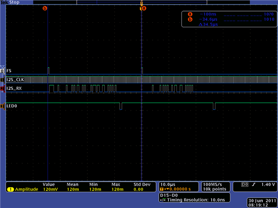
I have the i2s slave configured for ping pong DMA and interrupt driven operation. (see attached files).

The C5515 usb stick hardware is connected to an external sensor device that sends frames of data every 34.4 usec  The incoming clock rate from the external sensor is 2.5 MHz. i2s transfers 64 bits for stereo and DSP format  (32 bits for left + 32 bits right)

I have instrumented an LED on the board to indicate when the DMA interrupt gets serviced. There is a measure latency of 1 usec after the last bit sent by the sensor and 26 usec after the frame sync. The second frame sync comes in 10 usec after I've serviced the interrupt and I don't get a DMA for the next frame. Instead, I only get data from Frame 1.  Every DMA transfer gets frame 1 values and I don't see the interrupt service routine getting called after the frame 2 has been received.

Why don't I get frame #2 values?

I have the sensor configured to repeat the same pattern every two frames. Frame 1 contains 0xF080 1234 5678 9ABC, Frame 2 contains 0x0040 AAAA 5555 AAAA

WHen I look at the I2s registers I can see both patterns being updated in the registers. WHen I run the code I can see that the DMA controller is in fact setting the ping and pong bits.


/*  ============================================================================
 *   Copyright (c) Texas Instruments Inc 2002, 2003, 2004, 2005, 2008
 *
 *   Use of this software is controlled by the terms and conditions found in the
 *   license agreement under which this software has been supplied.
 *  ============================================================================
 */

/** @file csl_i2s_DmaExample.c
 *
 *  @brief Test code to verify the CSL I2S functionality in DMA mode
 *
 *
 * \page    page6  I2S EXAMPLE DOCUMENTATION
 *
 * \section I2S2   I2S EXAMPLE2 - DMA MODE TEST
 *
 * \subsection I2S2x    TEST DESCRIPTION:
 *		This test verifies the operation of CSL I2S module in DMA mode.
 * I2S module on C5505/C5515 DSP is used to exchange the audio data between
 * the audio codec and DSP.
 *
 * Testing of the I2S with the audio codec is not possible as codec is not
 * part of the CSL package. This test verifies the I2S operation in loopback
 * mode. In loopback mode of operation data written to the I2S data transmit
 * registers will be transmitted to the I2S data receive registers. CSL DMA
 * module should be configured for the I2S Tx and Rx operations.
 * DMA module is used to transfer the data between CPU memory and I2S data
 * registers. I2S is configured to master mode, stereo, 16bit data length and
 * to loop back mode. Due to word swap behavior of the DMA while transferring
 * the data to/from I2S, I2S write data buffer should be word swapped before
 * transferring it to the I2S registers. In case of I2S no word swap is
 * required on the data received due internal word swap by the I2S in loopback
 * mode. I2S data transfer is enabled and DMA is started using DMA_start() API.
 * DMA writes the data to the I2s Tx registers. After successful completion of
 * write operation DMA is configured for Rx operation and again started to read
 * the data from I2S Rx registers. I2S write and read buffers are compared for
 * the data verification.
 *
 * NOTE: THIS TEST HAS BEEN DEVELOPED TO WORK WITH CHIP VERSIONS C5505 AND
 * C5515. MAKE SURE THAT PROPER CHIP VERSION MACRO IS DEFINED IN THE FILE
 * c55xx_csl\inc\csl_general.h.
 *
 * \subsection I2S2y    TEST PROCEDURE:
 *  @li Open the CCS and connect the target (C5505/C5515 EVM)
 *  @li Open the project "CSL_I2S_DMAExampale_Out.pjt" and build it
 *  @li Load the program on to the target
 *  @li Set the PLL frequency to 12.288MHz
 *  @li Run the program and observe the test result
 *  @li Repeat the test at PLL frequencies 40, 60, 75 and 100MHz
 *  @li Repeat the test in Release mode
 *
 * \subsection I2S2z    TEST RESULT:
 *  @li All the CSL APIs should return success
 *  @li Read and write data buffer comparison should be successful.
 *
 * ============================================================================
 */

/* ============================================================================
 * Revision History
 * ================
 * 05-Sep-2008 Created
 * ============================================================================
 */
#include "csl_gpio.h"
#include "csl_dma.h"
#include "csl_i2s.h"
#include "csl_intc.h" // DJH added for CSL interrupt interface
#include <csl_general.h>
#include <stdio.h>

/* Reference the start of the interrupt vector table */
extern void VECSTART(void);

#ifdef ALGEBRAIC
#define HAL_XF_LED_ON    asm("\tBIT (ST1,#ST1_XF) = #1   ;====> C SOURCE INLINE ASSEMBLY");
#define HAL_XF_LED_OFF   asm("\tBIT (ST1,#ST1_XF) = #0   ;====> C SOURCE INLINE ASSEMBLY");

#else // ALGEBRAIC
#define HAL_XF_LED_ON    asm("\tbset XF;====> C SOURCE INLINE ASSEMBLY")
#define HAL_XF_LED_OFF   asm("\tbclr XF;====> C SOURCE INLINE ASSEMBLY") 
#endif // ALGEBRAIC


#define CSL_TEST_FAILED         (1)
#define CSL_TEST_PASSED         (0)
#define CSL_DMA0_CH0            (0)
#define kDMA_I2S2_PING_DBLWORDS (1)
#define CSL_I2S_DMA_BUF_LEN		(kDMA_I2S2_PING_DBLWORDS*2)     // (1) DJH 1 was Default value for demo. changed to 2 for both ping and pong

CSL_DMA_ChannelObj dmaObj;

CSL_DMA_Handle dmaLeftTxHandle;
CSL_DMA_Handle dmaRightTxHandle;
CSL_DMA_Handle dmaLeftRxHandle;
CSL_DMA_Handle dmaRightRxHandle;
CSL_DMA_Config dmaConfig;
#pragma DATA_ALIGN(i2sDmaWriteLeftBuff, 8); // 8 to Align to 64 bit boundary. Why not align to a 32 bit boundary???
Uint32 i2sDmaWriteLeftBuff[CSL_I2S_DMA_BUF_LEN] = {0xDEADBEEF};
#pragma DATA_ALIGN(i2sDmaWriteRightBuff, 8);
Uint32 i2sDmaWriteRightBuff[CSL_I2S_DMA_BUF_LEN] = {0x12345678};
#pragma DATA_ALIGN(i2sDmaReadLeftBuff, 8);
Uint32 i2sDmaReadLeftBuff[CSL_I2S_DMA_BUF_LEN] = {0x00000000};
#pragma DATA_ALIGN(i2sDmaReadRightBuff, 8);
Uint32 i2sDmaReadRightBuff[CSL_I2S_DMA_BUF_LEN] = {0x00000000};

// DJH added sensor data buffers to hold multiple samples
#define  SENSORDATA_BUFLEN 256
static volatile Uint32 mSensorBufferLeft[SENSORDATA_BUFLEN];
static volatile Uint32 mSensorBufferRight[SENSORDATA_BUFLEN];

/* Protype declaration for ISR function */
static interrupt void dma_isr(void);


/*
	This is functionality is to configure DMA
	for the source and destination address.

	Function returns:
	CSL_DMA_Handle              - Valid handler
	NULL                        - Invalid handler
*/

CSL_DMA_Handle CSL_configDmaForI2s(CSL_DMAChanNum    chanNum)
{
	CSL_DMA_Handle    dmaHandle;
	CSL_Status        status;
//	ioport volatile CSL_SysRegs		  *sysRegs;

	//sysRegs = (CSL_SysRegs *)CSL_SYSCTRL_REGS;

#if 0
    // DJH no need to do this because DMA_Init does this for us
	/*enable the corresponding DMA clock from PCGCR Registers*/
    CSL_FINS(sysRegs->PCGCR1, SYS_PCGCR1_DMA0CG, CSL_SYS_PCGCR1_DMA0CG_ACTIVE);
	CSL_FINS(sysRegs->PCGCR2, SYS_PCGCR2_DMA1CG, CSL_SYS_PCGCR2_DMA1CG_ACTIVE);
	CSL_FINS(sysRegs->PCGCR2, SYS_PCGCR2_DMA2CG, CSL_SYS_PCGCR2_DMA2CG_ACTIVE);
	CSL_FINS(sysRegs->PCGCR2, SYS_PCGCR2_DMA3CG, CSL_SYS_PCGCR2_DMA3CG_ACTIVE);
#endif

	dmaHandle = DMA_open(chanNum, &dmaObj,&status);
    if (dmaHandle == NULL)
    {
        printf("DMA_open() Failed \n");
        dmaHandle = NULL;
    }

	status = DMA_config(dmaHandle, &dmaConfig);
    if (status != CSL_SOK)
    {
        printf("DMA_config() Failed \n");
        dmaHandle = NULL;
    }

    return(dmaHandle);
}

static CSL_GpioObj    gpioObj;
static CSL_GpioObj    *hGpio;
// LEDs controlled via IOOUTDATA1
#define LED0_MASK 0x4000
#define LED1_MASK 0x8000

Int16
BoardSetup(void) {
    Int16 			status = CSL_TEST_FAILED;
    CSL_GpioConfig    config;
    /* Open GPIO module */
    hGpio = GPIO_open(&gpioObj, &status);
    if((NULL == hGpio) || (CSL_SOK != status))
    {
        printf("GPIO_open failed\n");
        return(CSL_TEST_FAILED);
    }
	else
	{
		printf("GPIO_open Successful\n");
	}
	    /* Configure the GPIO module */
	    // This code assumes the PPMODE is either MODE1 or MODE6 to support GPIO pins
    config.GPIODIRL     = 0xD001;   // ensure bit 14 and 15, DS5 & DS4  LEDs as output
    config.GPIODIRH     = 0x0403; 
    config.GPIOINTENAL  = 0x0000;   // no interrupts or triggers
    config.GPIOINTENAH  = 0x0000;
	config.GPIOINTTRIGL = 0x0000;
	config.GPIOINTTRIGH = 0x0000;

    status = GPIO_config(hGpio, &config);
    if(CSL_SOK != status)
    {
        printf("GPIO_config failed\n");
        return(CSL_TEST_FAILED);
    }
	else
	{
		printf("GPIO_config Successful\n");
	}
	// turn leds off (write 1's)
	CSL_GPIO_REGS->IOOUTDATA1 |= (LED0_MASK | LED1_MASK);
	return status;
}


/*
	This is functionality to receive data via the slave interface
	in stereo, DSP format, and via DMA

	Function returns:
	CSL_TEST_FAILED                -Failure
	CSL_TEST_PASSED                -Success
*/
Int16 i2s_DMA_sampleSlave(void)
{
	Int16 			status = CSL_TEST_FAILED;
	Int16 			result;
	CSL_I2sHandle	hI2s;
	I2S_Config		hwConfig;
	Uint16 			looper;


    IRQ_globalDisable();

	IRQ_clearAll();

	IRQ_disableAll();

	IRQ_setVecs((Uint32)&VECSTART);
	IRQ_clear(DMA_EVENT);

	IRQ_plug (DMA_EVENT, &dma_isr);

    // DJH move the DMA_Init here to clear out any residual DMA configuration
    // and we do it before we reenable interrupts
    status = DMA_init();
    if (status != CSL_SOK)
    {
        printf("DMA_init() Failed \n");
    }

	IRQ_enable(DMA_EVENT);
	IRQ_globalEnable();


	/* Initialize data buffers */
	for(looper=0; looper < CSL_I2S_DMA_BUF_LEN; looper++)
	{
		//i2sDmaWriteLeftBuff[looper] = 0x12345678;
		i2sDmaReadLeftBuff[looper]	= 0;
		//i2sDmaWriteRightBuff[looper] = 0x12345678;
		i2sDmaReadRightBuff[looper]	= 0;
	}

	for(looper=0; looper < SENSORDATA_BUFLEN; looper++)
	{
      mSensorBufferRight[looper] = mSensorBufferLeft[looper] = 0;
	}

	/** Open the device with instance 2							*/
	hI2s = I2S_open(I2S_INSTANCE2, DMA_POLLED, I2S_CHAN_STEREO);
	if(NULL == hI2s)
	{
		status = CSL_TEST_FAILED;
		return (status);
	}
	else
	{
		printf ("I2S Module Instance opened successfully\n");
	}

    /** Set the value for the configure structure               */
    hwConfig.dataType           = I2S_STEREO_ENABLE;
//#if _UNITTEST_I2S_
//    hwConfig.loopBackMode       = I2S_LOOPBACK_ENABLE;
//    hwConfig.i2sMode            = I2S_MASTER;
//#else
    hwConfig.loopBackMode       = I2S_LOOPBACK_DISABLE;
    hwConfig.i2sMode            = I2S_SLAVE;
//#endif // _UNITTEST_I2S_
    hwConfig.fsPol              = I2S_FSPOL_LOW;
    hwConfig.clkPol             = I2S_RISING_EDGE;
    hwConfig.datadelay          = I2S_DATADELAY_TWOBIT;
    hwConfig.datapack           = I2S_DATAPACK_DISABLE;
    hwConfig.signext            = I2S_SIGNEXT_DISABLE;
    hwConfig.wordLen            = I2S_WORDLEN_32;
    hwConfig.clkDiv             = I2S_CLKDIV4;
    hwConfig.fsDiv              = I2S_FSDIV32;
    hwConfig.FError             = I2S_FSERROR_DISABLE;
    hwConfig.OuError            = I2S_OUERROR_DISABLE;

	/** Configure hardware registers							*/
	result = I2S_setup(hI2s, &hwConfig);
	if(result != CSL_SOK)
	{
		status = CSL_TEST_FAILED;
		return (status);
	}
	else
	{
		printf ("I2S Module Configured successfully\n");
	}
    // Set the DSP Format flag..The i2s driver by default clears this bit
    hI2s->hwRegs->I2SSCTRL |= CSL_I2S_I2SSCTRL_FRMT_MASK;
    
    // Clear the interrupt mask bits since we're using DMA per 1.2.14.1 of SPRUFX4
    hI2s->hwRegs->I2SINTMASK = (Uint16)CSL_I2S_I2SINTMASK_RESETVAL;

	/* Configure DMA channel 4  for I2S2 Read of left channel*/
#if (defined(CHIP_C5505_C5515) || defined(CHIP_C5504_C5514))
	dmaConfig.pingPongMode = CSL_DMA_PING_PONG_DISABLE;
#endif
	dmaConfig.autoMode     = CSL_DMA_AUTORELOAD_ENABLE;
	dmaConfig.burstLen     = CSL_DMA_TXBURST_1WORD;  // 1x 32 bit transfer for i2s event
	dmaConfig.trigger      = CSL_DMA_EVENT_TRIGGER;
	dmaConfig.dmaEvt       = CSL_DMA_EVT_I2S2_RX;
	dmaConfig.dmaInt       = CSL_DMA_INTERRUPT_ENABLE;
	dmaConfig.chanDir      = CSL_DMA_READ;
	dmaConfig.trfType      = CSL_DMA_TRANSFER_IO_MEMORY;
	dmaConfig.dataLen      = CSL_I2S_DMA_BUF_LEN*4; // convert from 32 bit word count to bytes
	dmaConfig.srcAddr      = (Uint32)&(hI2s->hwRegs->I2SRXLT0); // 0x2A28 
	dmaConfig.destAddr     = (Uint32)i2sDmaReadLeftBuff;
	dmaLeftRxHandle = CSL_configDmaForI2s(CSL_DMA_CHAN4);
	if(dmaLeftRxHandle == NULL)
	{
		printf("DMA Config for I2S Read Failed!\n!");
		return(CSL_TEST_FAILED);
	}
	
	/* Configure DMA channel 5  for I2S2 Read of right channel */
#if (defined(CHIP_C5505_C5515) || defined(CHIP_C5504_C5514))
	dmaConfig.pingPongMode = CSL_DMA_PING_PONG_DISABLE;
#else
    // DJH sanity check because we want to use the C5515
    #error "Must define CHIP_C5505_C5515"
#endif
#if _USE_I2S_RIGHT 
    // Change the config parameters as necessary for the right channel
	dmaConfig.srcAddr      = (Uint32)&(hI2s->hwRegs->I2SRXRT0); // 0x2A28 
	dmaConfig.destAddr     = (Uint32)i2sDmaReadRightBuff;
	dmaRightRxHandle = CSL_configDmaForI2s(CSL_DMA_CHAN5);
	if(dmaRightRxHandle == NULL)
	{
		printf("DMA Config for I2S Read Failed!\n!");
		return(CSL_TEST_FAILED);
	}	
#endif 

	I2S_transEnable(hI2s, TRUE);
	status = DMA_start(dmaLeftRxHandle);
	if(status != CSL_SOK)
	{
		printf("I2S Dma Start Left Failed!!\n");
		return(result);
	}
#if _USE_I2S_RIGHT
	status = DMA_start(dmaRightRxHandle);
	if(status != CSL_SOK)
	{
		printf("I2S Dma Start Right Failed!!\n");
		return(result);
	}
#endif
    // run forever here    	
    for(;;) {
       int ledState;
       volatile int rtcSecSnap;
        
    
        rtcSecSnap =CSL_RTC_REGS->RTCSEC;
        if (ledState) {
            HAL_XF_LED_ON;
        } else {
            HAL_XF_LED_OFF;
        }
        ledState = !ledState;
        while (rtcSecSnap==CSL_RTC_REGS->RTCSEC) {
          // do nothing    
        }	
    }
}


/*
	This is functionality Transmit  and
	receive data with DMA mode.
	The data transmission and receive happen in stereo mode.

	Function returns:
	CSL_TEST_FAILED                -Failure
	CSL_TEST_PASSED                -Success
*/
Int16 i2s_DMA_sample(void)
{
	Int16 			status = CSL_TEST_FAILED;
	Int16 			result;
	CSL_I2sHandle	hI2s;
	I2S_Config		hwConfig;
	Uint16 			looper;

	/* Initialize data buffers */
	for(looper=0; looper < CSL_I2S_DMA_BUF_LEN; looper++)
	{
		i2sDmaWriteLeftBuff[looper] = 0x12345678;
		i2sDmaReadLeftBuff[looper]	= 0;
		i2sDmaWriteRightBuff[looper] = 0x12345678;
		i2sDmaReadRightBuff[looper]	= 0;
	}

	/* On C5505/C5515 DSP DMA swaps the words in the source buffer
	   before transferring it to the I2S registers. No data mismatch is
	   observed When the  write and read operations are done in DMA mode
	   as the word swap occurs in both the operations.
	   There will be data mismatch if data write is in DMA mode
	   and read is in polling mode or vice versa.
	   To ensure that the data will be written to memory properly in DMA mode
	   words in the write buffer are swapped by software. During DMA transfer
	   DMA hardware again will do a word swap which will bring the data buffer
	   back to original values. Word swap is not required for read
	   buffer after read operation in DMA mode as I2S hardware will do
	   a word swap on the data before looping it back to receive registers.
	   This is peculiar behavior of the I2S HW in loopback mode
	 */
	/* Swap words in I2S write buffer */
	result = DMA_swapWords((Uint16*)i2sDmaWriteLeftBuff, 2*CSL_I2S_DMA_BUF_LEN);
	if(result != CSL_SOK)
	{
		printf ("DMA word swap API failed\n");
		status = CSL_TEST_FAILED;
		return (status);
	}

	/** Open the device with instance 0							*/
	hI2s = I2S_open(I2S_INSTANCE0, DMA_POLLED, I2S_CHAN_STEREO);
	if(NULL == hI2s)
	{
		status = CSL_TEST_FAILED;
		return (status);
	}
	else
	{
		printf ("I2S Module Instance opened successfully\n");
	}

	/** Set the value for the configure structure				*/
	hwConfig.dataType 			= I2S_STEREO_ENABLE;
	hwConfig.loopBackMode 		= I2S_LOOPBACK_ENABLE;
	hwConfig.fsPol 				= I2S_FSPOL_LOW;
	hwConfig.clkPol				= I2S_FALLING_EDGE;
	hwConfig.datadelay			= I2S_DATADELAY_ONEBIT;
	hwConfig.datapack			= I2S_DATAPACK_ENABLE;
	hwConfig.signext			= I2S_SIGNEXT_DISABLE;
	hwConfig.wordLen			= I2S_WORDLEN_16;
	hwConfig.i2sMode			= I2S_MASTER;
	hwConfig.clkDiv				= I2S_CLKDIV4;
	hwConfig.fsDiv				= I2S_FSDIV32;
	hwConfig.FError				= I2S_FSERROR_DISABLE;
	hwConfig.OuError			= I2S_OUERROR_DISABLE;

	/** Configure hardware registers							*/
	result = I2S_setup(hI2s, &hwConfig);
	if(result != CSL_SOK)
	{
		status = CSL_TEST_FAILED;
		return (status);
	}
	else
	{
		printf ("I2S Module Configured successfully\n");
	}

	/* Configure DMA channel  for I2S write */
#if (defined(CHIP_C5505_C5515) || defined(CHIP_C5504_C5514))
	dmaConfig.pingPongMode = CSL_DMA_PING_PONG_DISABLE;
#endif
	dmaConfig.autoMode     = CSL_DMA_AUTORELOAD_DISABLE;
	dmaConfig.burstLen     = CSL_DMA_TXBURST_1WORD;
	dmaConfig.trigger      = CSL_DMA_EVENT_TRIGGER;
	dmaConfig.dmaEvt       = CSL_DMA_EVT_I2S0_TX;
	dmaConfig.dmaInt       = CSL_DMA_INTERRUPT_DISABLE;
	dmaConfig.chanDir      = CSL_DMA_WRITE;
	dmaConfig.trfType      = CSL_DMA_TRANSFER_IO_MEMORY;
	dmaConfig.dataLen      = 4;
	dmaConfig.srcAddr      = (Uint32)i2sDmaWriteLeftBuff;
	dmaConfig.destAddr     = (Uint32)(0x2808);
	dmaLeftTxHandle = CSL_configDmaForI2s(CSL_DMA_CHAN0);
	if(dmaLeftTxHandle == NULL)
	{
		printf("DMA Config for I2S Write Failed!\n!");
		return(CSL_TEST_FAILED);
	}

	I2S_transEnable(hI2s, TRUE);

	status = DMA_start(dmaLeftTxHandle);
	if(status != CSL_SOK)
	{
		printf("I2S Dma Write Failed!!\n");
		return(result);
	}
	while(DMA_getStatus(dmaLeftTxHandle));

	/* Configure DMA channel  for I2S write */
#if (defined(CHIP_C5505_C5515) || defined(CHIP_C5504_C5514))
	dmaConfig.pingPongMode = CSL_DMA_PING_PONG_DISABLE;
#endif
	dmaConfig.autoMode     = CSL_DMA_AUTORELOAD_DISABLE;
	dmaConfig.burstLen     = CSL_DMA_TXBURST_1WORD;
	dmaConfig.trigger      = CSL_DMA_EVENT_TRIGGER;
	dmaConfig.dmaEvt       = CSL_DMA_EVT_I2S0_TX;
	dmaConfig.dmaInt       = CSL_DMA_INTERRUPT_DISABLE;
	dmaConfig.chanDir      = CSL_DMA_WRITE;
	dmaConfig.trfType      = CSL_DMA_TRANSFER_IO_MEMORY;
	dmaConfig.dataLen      = 4;
	dmaConfig.srcAddr      = (Uint32)i2sDmaWriteRightBuff;
	dmaConfig.destAddr     = (Uint32)(0x280C);
	dmaRightTxHandle = CSL_configDmaForI2s(CSL_DMA_CHAN0);
	if(dmaRightTxHandle == NULL)
	{
		printf("DMA Config for I2S Write Failed!\n!");
		return(CSL_TEST_FAILED);
	}

	I2S_transEnable(hI2s, TRUE);

	status = DMA_start(dmaRightTxHandle);
	if(status != CSL_SOK)
	{
		printf("I2S Dma Write Failed!!\n");
		return(result);
	}
	while(DMA_getStatus(dmaRightTxHandle));

	/* Configure DMA channel  for I2S Read */
#if (defined(CHIP_C5505_C5515) || defined(CHIP_C5504_C5514))
	dmaConfig.pingPongMode = CSL_DMA_PING_PONG_DISABLE;
#endif
	dmaConfig.autoMode     = CSL_DMA_AUTORELOAD_DISABLE;
	dmaConfig.burstLen     = CSL_DMA_TXBURST_1WORD;
	dmaConfig.trigger      = CSL_DMA_EVENT_TRIGGER;
	dmaConfig.dmaEvt       = CSL_DMA_EVT_I2S0_RX;
	dmaConfig.dmaInt       = CSL_DMA_INTERRUPT_DISABLE;
	dmaConfig.chanDir      = CSL_DMA_READ;
	dmaConfig.trfType      = CSL_DMA_TRANSFER_IO_MEMORY;
	dmaConfig.dataLen      = 4;
	dmaConfig.srcAddr      = (Uint32)(0x2828);
	dmaConfig.destAddr     = (Uint32)i2sDmaReadLeftBuff;
	dmaLeftRxHandle = CSL_configDmaForI2s(CSL_DMA_CHAN0);
	if(dmaLeftRxHandle == NULL)
	{
		printf("DMA Config for I2S Read Failed!\n!");
		return(CSL_TEST_FAILED);
	}

	status = DMA_start(dmaLeftRxHandle);
	if(status != CSL_SOK)
	{
		printf("I2S Dma Read Failed!!\n");
		return(result);
	}
	while(DMA_getStatus(dmaLeftRxHandle));

	/* Configure DMA channel  for I2S Read */
#if (defined(CHIP_C5505_C5515) || defined(CHIP_C5504_C5514))
	dmaConfig.pingPongMode = CSL_DMA_PING_PONG_DISABLE;
#endif
	dmaConfig.autoMode     = CSL_DMA_AUTORELOAD_DISABLE;
	dmaConfig.burstLen     = CSL_DMA_TXBURST_1WORD;
	dmaConfig.trigger      = CSL_DMA_EVENT_TRIGGER;
	dmaConfig.dmaEvt       = CSL_DMA_EVT_I2S0_RX;
	dmaConfig.dmaInt       = CSL_DMA_INTERRUPT_DISABLE;
	dmaConfig.chanDir      = CSL_DMA_READ;
	dmaConfig.trfType      = CSL_DMA_TRANSFER_IO_MEMORY;
	dmaConfig.dataLen      = 4;
	dmaConfig.srcAddr      = (Uint32)(0x282C);
	dmaConfig.destAddr     = (Uint32)i2sDmaReadRightBuff;
	dmaRightRxHandle = CSL_configDmaForI2s(CSL_DMA_CHAN0);
	if(dmaRightRxHandle == NULL)
	{
		printf("DMA Config for I2S Read Failed!\n!");
		return(CSL_TEST_FAILED);
	}

	I2S_transEnable(hI2s, TRUE);

	status = DMA_start(dmaRightRxHandle);
	if(status != CSL_SOK)
	{
		printf("I2S Dma Read Failed!!\n");
		return(result);
	}
	while(DMA_getStatus(dmaRightRxHandle));

	I2S_transEnable(hI2s, FALSE);
	/** Reset the registers										*/
	result = I2S_reset(hI2s);

	if(result != CSL_SOK)
	{
		status = CSL_TEST_FAILED;
		return (status);
	}
	else
	{
		printf ("I2S Reset Successful\n");
	}

	/** Close the operation										*/
	result = I2S_close(hI2s);

	if(result != CSL_SOK)
	{
		status = CSL_TEST_FAILED;
		return (status);
	}
	else
	{
		printf ("I2S Close Successful\n");
	}

	/* Swap words in I2S write buffer
	   This will make the data in write buffer get back to original values
	   after that write buffer can be used for validating the read buffer
	   This sep is required only incase of comparing read and write buffers */
	result = DMA_swapWords((Uint16*)i2sDmaWriteLeftBuff, 2*CSL_I2S_DMA_BUF_LEN);
	if(result != CSL_SOK)
	{
		printf ("DMA word swap API failed\n");
		status = CSL_TEST_FAILED;
		return (status);
	}

	/** Compare the read and write buffer						*/
	for(looper=0; looper < CSL_I2S_DMA_BUF_LEN; looper++)
	{
		if(i2sDmaWriteLeftBuff[looper] != i2sDmaReadLeftBuff[looper])
		{
			printf("I2S Read & Write Buffers doesn't Match!!!\n");
			status = CSL_TEST_FAILED;
			return(status);
		}
	}

	if(looper == CSL_I2S_DMA_BUF_LEN)
	{
		printf("I2S Read & Write Buffers Match!!!\n");
	}

	status = CSL_TEST_PASSED;
	return (status);
}

/*
 This is the main function to call sample program
*/
   /////INSTRUMENTATION FOR BATCH TESTING -- Part 1 --   
   /////  Define PaSs_StAtE variable for catching errors as program executes.
   /////  Define PaSs flag for holding final pass/fail result at program completion.
        volatile Int16 PaSs_StAtE = 0x0001; // Init to 1. Reset to 0 at any monitored execution error.
        volatile Int16 PaSs = 0x0000; // Init to 0.  Updated later with PaSs_StAtE when and if
   /////                                  program flow reaches expected exit point(s).
   /////
void main(void)
{
	Int16    status;
    BoardSetup();
	printf("CSL I2S DMA MODE TEST!\n\n");

	// status = i2s_DMA_sample();
    status = i2s_DMA_sampleSlave();
	if(status != CSL_TEST_PASSED)
	{
		printf("\nCSL I2S DMA MODE TEST FAILED!!\n\n");
   /////INSTRUMENTATION FOR BATCH TESTING -- Part 2 --   
   /////  Reseting PaSs_StAtE to 0 if error detected here.
        PaSs_StAtE = 0x0000; // Was intialized to 1 at declaration.
   /////
	}
	else
	{
		printf("\nCSL I2S DMA MODE TEST PASSED!\n\n");
	}
   /////INSTRUMENTATION FOR BATCH TESTING -- Part 3 -- 
   /////  At program exit, copy "PaSs_StAtE" into "PaSs".
        PaSs = PaSs_StAtE; //If flow gets here, override PaSs' initial 0 with 
   /////                   // pass/fail value determined during program execution.
   /////  Note:  Program should next exit to C$$EXIT and halt, where DSS, under
   /////   control of a host PC script, will read and record the PaSs' value.  
   /////
}

static volatile Uint16 mnPingErr = 0;
static volatile Uint16 mPongLeftLast = 0;
static volatile Uint16 mPongRightLast = 0;


static volatile Uint16 mLeftIdx = 0;
static volatile Uint16 mRightIdx = 0;
static volatile Uint32 isrEntryCount = 0;
interrupt void dma_isr(void)
{
	int idx;
    int ifrValue;
    int pong; //=CSL_DMA_DMACH0TCR2_LTSTATUS_MASK for pong, =0 for ping
  	ifrValue = CSL_SYSCTRL_REGS->DMAIFR;
    //HAL_XF_LED_OFF;
    // turn led on'
    CSL_GPIO_REGS->IOOUTDATA1 &= ~LED0_MASK;

#if 1
    // Determine if the ping or pong register was filled
	  if (CSL_SYS_DMAIFR_DMA1CH0IF_MASK & ifrValue) {
        // we do the equivalent of DMA_getLastTransferType() to
        // determine if it's the ping or the pong buffer
        pong = (CSL_DMA1_REGS->DMACH0TCR2 & CSL_DMA_DMACH0TCR2_LTSTATUS_MASK);
        idx = pong ? kDMA_I2S2_PING_DBLWORDS : 0; // LTSTATUS=1 for pong, =0 for ping
        if (mPongLeftLast==pong) {
          mnPingErr++;  
        }
        
        mPongLeftLast = pong;
        // per the audio filter demo provided by TI, we must manually set the new destination
        // address 
        //CSL_DMA1_REGS->DMACH0TCR2
        
        // copy the data into the 
        mSensorBufferLeft[mLeftIdx] = i2sDmaReadLeftBuff[idx];
        mLeftIdx = (mLeftIdx + 1)% SENSORDATA_BUFLEN;
        CSL_SYSCTRL_REGS->DMAIFR = CSL_SYS_DMAIFR_DMA1CH0IF_MASK;
	  } 
#if 0
    // Determine if the ping or pong register was filled
	  if (CSL_SYS_DMAIFR_DMA1CH1IF_MASK & ifrValue) {
        // we do the equivalent of DMA_getLastTransferType() to
        // determine if it's the ping or the pong buffer
        pong = (CSL_DMA1_REGS->DMACH1TCR2 & CSL_DMA_DMACH1TCR2_LTSTATUS_MASK);
        idx = pong ? kDMA_I2S2_PING_DBLWORDS : 0; // LTSTATUS=1 for pong, =0 for ping
        if (mPongRightLast==pong) {
          mnPingErr++;  
        }
        mPongRightLast = pong;
        // copy the data into the our sensor buffer to just look at samples
        mSensorBufferRight[mRightIdx] = i2sDmaReadRightBuff[idx];
        mRightIdx = (mRightIdx + 1) % SENSORDATA_BUFLEN;
        CSL_SYSCTRL_REGS->DMAIFR = CSL_SYS_DMAIFR_DMA1CH1IF_MASK;
	  } 
#endif
#endif 
	// CSL_SYSCTRL_REGS->DMAIFR = ifrValue;  // Clear the bits for this dma channel being service
	//++count;
	++isrEntryCount;
	// turn led0 off
    CSL_GPIO_REGS->IOOUTDATA1 |= LED0_MASK;
}
/********************************************************************/
/* usbstk5515.gel                                                   */
/* Version 1.00                                                     */
/*                                                                  */
/* This GEL file is to be used with the 5515 eZDSP USB STICK.       */
/* Changes may be required to support specific hardware designs.    */
/*                                                                  */
/* Code Composer Studio supports six reserved GEL functions that    */
/* automatically get executed if they are defined. They are:        */
/*                                                                  */
/* StartUp()              - Executed whenever CCS is invoked        */
/* OnReset()              - Executed after Debug->Reset CPU         */
/* OnRestart()            - Executed after Debug->Restart           */
/* OnPreFileLoaded()      - Executed before File->Load Program      */
/* OnFileLoaded()         - Executed after File->Load Program       */
/* OnTargetConnect()      - Executed after Debug->Connect           */
/*                                                                  */
/*   Version History                                                */
/*     v0.01        Initial Release                                 */
/*     v1.00        Added PLL frequencies                           */
/*     v2.00        CHanged frequency to be 120 MHz
/********************************************************************/
StartUp()
{
    c5515_MapInit();
}

/*--------------------------------------------------------------*/
/* OnTargetConnect() -- this function is called after a target  */
/* connect.                                                     */
/*--------------------------------------------------------------*/
OnTargetConnect()
{
    GEL_Reset();
    Peripheral_Reset();
    ProgramPLL_120MHz();
    /* ProgramPLL_100MHz(); */
    GEL_TextOut("Target Connection Complete.\n"); 
}

/*--------------------------------------------------------------*/
/* OnPreFileLoaded()                                            */
/* This function is called automatically when the 'Load Program'*/
/* Menu item is selected.                                       */
/*--------------------------------------------------------------*/
OnPreFileLoaded()
{
    /* Reset the CPU to clean up state */
    //GEL_Reset();
}

/*--------------------------------------------------------------*/
/* OnRestart()                                                  */
/* This function is executed before a file is restarted. Disable*/
/* interrupts and DMA from the current program so pending       */
/* events and transfers don't interfere with the new program.   */
/*--------------------------------------------------------------*/
OnRestart()
{
    /* Disable interrupts */
    *(int*)0x0003 = *(int*)0x0003 | 0x0800; // Set INTM
    *(int*)0x0000 = 0;      // Clear IER0
    *(int*)0x0000 = 0;      // Clear IER1
}

/*--------------------------------------------------------------*/
/* OnReset()                                                    */
/* This function is called by CCS when you do Debug->Resest.    */
/* The goal is to put the C55xx into a known good state with    */
/* respect to cache, dma and interrupts.                        */
/*--------------------------------------------------------------*/
OnReset( int nErrorCode )
{
}

/*--------------------------------------------------------------*/
/* OnFileLoaded()                                               */
/* This function is called by CCS when you do File->Load Program*/
/* The goal is to do in post file loaded configuration that may */
/* be needed.                                                   */
/*--------------------------------------------------------------*/
OnFileLoaded()
{
}

#define ESCR     0x1c33

#define SDTIMR1  0x1020 
#define SDTIMR2  0x1021 
#define SDCR1    0x1008 
#define SDCR2    0x1009
#define SDSRETR  0x103C
#define SDRCR    0x100C

#define PRCR     0x1C05 
#define PCGCR1   0x1c02
#define PCGCR2   0x1c03
#define PSRCR    0x1c04 

#define CLKCFGL  0x1c1e
#define CCR2     0x1c1f
#define CGCR1    0x1c20
#define CGCR2    0x1c21
#define CGCR3    0x1c22
#define CGCR4    0x1c23
#define CCSSR    0x1c24
#define IVPD     0x0049


// ***************************************************************************

/* Memory map based on MP/MC value (assume MP/MC = 0).    */
c5515_MapInit() {
    GEL_MapOn();
    GEL_MapReset();

    /*Program Space*/

    /* DARAM */
    GEL_MapAdd(0x0000C0,0,0x001F40,1,1);    /* DARAM0 */
    GEL_MapAdd(0x002000,0,0x002000,1,1);    /* DARAM1 */
    GEL_MapAdd(0x004000,0,0x002000,1,1);    /* DARAM2 */
    GEL_MapAdd(0x006000,0,0x002000,1,1);    /* DARAM3 */
    GEL_MapAdd(0x008000,0,0x002000,1,1);    /* DARAM4 */
    GEL_MapAdd(0x00A000,0,0x002000,1,1);    /* DARAM5 */
    GEL_MapAdd(0x00C000,0,0x002000,1,1);    /* DARAM6 */
    GEL_MapAdd(0x00E000,0,0x002000,1,1);    /* DARAM7 */

    /* SARAM */
    GEL_MapAdd(0x010000,0,0x002000,1,1);    /* SARAM0 */
    GEL_MapAdd(0x012000,0,0x002000,1,1);    /* SARAM1 */
    GEL_MapAdd(0x014000,0,0x002000,1,1);    /* SARAM2 */
    GEL_MapAdd(0x016000,0,0x002000,1,1);    /* SARAM3 */
    GEL_MapAdd(0x018000,0,0x002000,1,1);    /* SARAM4 */
    GEL_MapAdd(0x01A000,0,0x002000,1,1);    /* SARAM5 */
    GEL_MapAdd(0x01C000,0,0x002000,1,1);    /* SARAM6 */
    GEL_MapAdd(0x01E000,0,0x002000,1,1);    /* SARAM7 */
    GEL_MapAdd(0x020000,0,0x002000,1,1);    /* SARAM8 */
    GEL_MapAdd(0x022000,0,0x002000,1,1);    /* SARAM9 */
    GEL_MapAdd(0x024000,0,0x002000,1,1);    /* SARAM10 */
    GEL_MapAdd(0x026000,0,0x002000,1,1);    /* SARAM11 */
    GEL_MapAdd(0x028000,0,0x002000,1,1);    /* SARAM12 */
    GEL_MapAdd(0x02A000,0,0x002000,1,1);    /* SARAM13 */
    GEL_MapAdd(0x02C000,0,0x002000,1,1);    /* SARAM14 */
    GEL_MapAdd(0x02E000,0,0x002000,1,1);    /* SARAM15 */
    GEL_MapAdd(0x030000,0,0x002000,1,1);    /* SARAM16 */
    GEL_MapAdd(0x032000,0,0x002000,1,1);    /* SARAM17 */
    GEL_MapAdd(0x034000,0,0x002000,1,1);    /* SARAM18 */
    GEL_MapAdd(0x036000,0,0x002000,1,1);    /* SARAM19 */
    GEL_MapAdd(0x038000,0,0x002000,1,1);    /* SARAM20 */
    GEL_MapAdd(0x03A000,0,0x002000,1,1);    /* SARAM21 */
    GEL_MapAdd(0x03C000,0,0x002000,1,1);    /* SARAM22 */
    GEL_MapAdd(0x03E000,0,0x002000,1,1);    /* SARAM23 */
    GEL_MapAdd(0x040000,0,0x002000,1,1);    /* SARAM24 */
    GEL_MapAdd(0x042000,0,0x002000,1,1);    /* SARAM25 */
    GEL_MapAdd(0x044000,0,0x002000,1,1);    /* SARAM26 */
    GEL_MapAdd(0x046000,0,0x002000,1,1);    /* SARAM27 */
    GEL_MapAdd(0x048000,0,0x002000,1,1);    /* SARAM28 */
    GEL_MapAdd(0x04A000,0,0x002000,1,1);    /* SARAM29 */
    GEL_MapAdd(0x04C000,0,0x002000,1,1);    /* SARAM30 */
    GEL_MapAdd(0x04E000,0,0x002000,1,1);    /* SARAM31 */

    /* External-Memory */
    GEL_MapAdd(0x050000,0,0x7B0000,1,1);    /* External-SDRAM */
    GEL_MapAdd(0x800000,0,0x400000,1,1);    /* External-Async */
    GEL_MapAdd(0xC00000,0,0x200000,1,1);    /* External-Async */
    GEL_MapAdd(0xE00000,0,0x100000,1,1);    /* External-Async */
    GEL_MapAdd(0xF00000,0,0x0E0000,1,1);    /* External-Async */

    /* ROM */
    GEL_MapAdd(0xFE0000,0,0x008000,1,0);    /* SAROM0 */
    GEL_MapAdd(0xFE8000,0,0x008000,1,0);    /* SAROM1 */
    GEL_MapAdd(0xFF0000,0,0x008000,1,0);    /* SAROM2 */
    GEL_MapAdd(0xFF8000,0,0x008000,1,0);    /* SAROM3 */

    /* Data Space */

    /* DARAM */
    GEL_MapAdd(0x000000,1,0x000060,1,1);    /* MMRs */
    GEL_MapAdd(0x000060,1,0x000FA0,1,1);    /* DARAM0 */
    GEL_MapAdd(0x001000,1,0x001000,1,1);    /* DARAM1 */
    GEL_MapAdd(0x002000,1,0x001000,1,1);    /* DARAM2 */
    GEL_MapAdd(0x003000,1,0x001000,1,1);    /* DARAM3 */
    GEL_MapAdd(0x004000,1,0x001000,1,1);    /* DARAM4 */
    GEL_MapAdd(0x005000,1,0x001000,1,1);    /* DARAM5 */
    GEL_MapAdd(0x006000,1,0x001000,1,1);    /* DARAM6 */
    GEL_MapAdd(0x007000,1,0x001000,1,1);    /* DARAM7 */

    /* SARAM */
    GEL_MapAdd(0x008000,1,0x001000,1,1);    /* SARAM0 */
    GEL_MapAdd(0x009000,1,0x001000,1,1);    /* SARAM1 */
    GEL_MapAdd(0x00A000,1,0x001000,1,1);    /* SARAM2 */
    GEL_MapAdd(0x00B000,1,0x001000,1,1);    /* SARAM3 */
    GEL_MapAdd(0x00C000,1,0x001000,1,1);    /* SARAM4 */
    GEL_MapAdd(0x00D000,1,0x001000,1,1);    /* SARAM5 */
    GEL_MapAdd(0x00E000,1,0x001000,1,1);    /* SARAM6 */
    GEL_MapAdd(0x00F000,1,0x001000,1,1);    /* SARAM7 */
    GEL_MapAdd(0x010000,1,0x001000,1,1);    /* SARAM8 */
    GEL_MapAdd(0x011000,1,0x001000,1,1);    /* SARAM9 */
    GEL_MapAdd(0x012000,1,0x001000,1,1);    /* SARAM10 */
    GEL_MapAdd(0x013000,1,0x001000,1,1);    /* SARAM11 */
    GEL_MapAdd(0x014000,1,0x001000,1,1);    /* SARAM12 */
    GEL_MapAdd(0x015000,1,0x001000,1,1);    /* SARAM13 */
    GEL_MapAdd(0x016000,1,0x001000,1,1);    /* SARAM14 */
    GEL_MapAdd(0x017000,1,0x001000,1,1);    /* SARAM15 */
    GEL_MapAdd(0x018000,1,0x001000,1,1);    /* SARAM16 */
    GEL_MapAdd(0x019000,1,0x001000,1,1);    /* SARAM17 */
    GEL_MapAdd(0x01A000,1,0x001000,1,1);    /* SARAM18 */
    GEL_MapAdd(0x01B000,1,0x001000,1,1);    /* SARAM19 */
    GEL_MapAdd(0x01C000,1,0x001000,1,1);    /* SARAM20 */
    GEL_MapAdd(0x01D000,1,0x001000,1,1);    /* SARAM21 */
    GEL_MapAdd(0x01E000,1,0x001000,1,1);    /* SARAM22 */
    GEL_MapAdd(0x01F000,1,0x001000,1,1);    /* SARAM23 */
    GEL_MapAdd(0x020000,1,0x001000,1,1);    /* SARAM24 */
    GEL_MapAdd(0x021000,1,0x001000,1,1);    /* SARAM25 */
    GEL_MapAdd(0x022000,1,0x001000,1,1);    /* SARAM26 */
    GEL_MapAdd(0x023000,1,0x001000,1,1);    /* SARAM27 */
    GEL_MapAdd(0x024000,1,0x001000,1,1);    /* SARAM28 */
    GEL_MapAdd(0x025000,1,0x001000,1,1);    /* SARAM29 */
    GEL_MapAdd(0x026000,1,0x001000,1,1);    /* SARAM30 */
    GEL_MapAdd(0x027000,1,0x001000,1,1);    /* SARAM31 */

    /* External-Memory */
    GEL_MapAdd(0x028000,1,0x3D8000,1,1);    /* External-SDRAM */
    GEL_MapAdd(0x400000,1,0x200000,1,1);    /* External-Async */
    GEL_MapAdd(0x600000,1,0x100000,1,1);    /* External-Async */
    GEL_MapAdd(0x700000,1,0x080000,1,1);    /* External-Async */
    GEL_MapAdd(0x780000,1,0x070000,1,1);    /* External-Async */

    /* ROM */
    GEL_MapAdd(0x7F0000,1,0x004000,1,0);    /* SAROM0 */
    GEL_MapAdd(0x7F4000,1,0x004000,1,0);    /* SAROM1 */
    GEL_MapAdd(0x7F8000,1,0x004000,1,0);    /* SAROM2 */
    GEL_MapAdd(0x7FC000,1,0x004000,1,0);    /* SAROM3 */

    /* IO Space */
    GEL_MapAdd(0x0000,2,0xFFFF,1,1);        /* XPORT */
}

Peripheral_Reset()
{
    int i;

    *(short *)PSRCR@IO = 0x0020;
    *(short *)PRCR@IO  = 0x00BB;

    for(i=0;i<0xff;i++);
    *(short *)IVPD@data = 0x027F; // Load interrupt vector pointer
    GEL_TextOut("Reset Peripherals is complete.\n");
}

ProgramPLL_100MHz() {
    int i;

    GEL_TextOut("Configuring PLL (100 MHz).\n");
    /* Enable clocks to all peripherals */
    *(short *)PCGCR1@IO = 0x0;
    *(short *)PCGCR2@IO = 0x0;

    /* Bypass PLL */
    *(short *)CCR2@IO = 0x0;

    /* Set CLR_CNTL = 0 */
    *(short *)CGCR1@IO = *(short *)CGCR1@IO & 0x7FFF;

    *(short *)CGCR1@IO =  0x8BE8;
    *(short *)CGCR2@IO =  0x8000;
    *(short *)CGCR3@IO =  0x0806;
    *(short *)CGCR4@IO =  0x0000; 

    /* Wait for PLL lock */
    for(i=0;i<0x7fff;i++);

    /* Switch to PLL clk */ 
    *(short *)CCR2@IO = 0x1;

    GEL_TextOut("PLL Init Done.");
    
}

ProgramPLL_120MHz() {
    int i;

    GEL_TextOut("Configuring PLL (120 MHz).\n");
    /* Enable clocks to all peripherals */
    *(short *)PCGCR1@IO = 0x0;
    *(short *)PCGCR2@IO = 0x0;

    /* Bypass PLL */
    *(short *)CCR2@IO = 0x0;

    /* Set CLR_CNTL = 0 */
    *(short *)CGCR1@IO = *(short *)CGCR1@IO & 0x7FFF;

    *(short *)CGCR1@IO =  0x8E4B;
    *(short *)CGCR2@IO =  0x8000;
    *(short *)CGCR3@IO =  0x0806;
    *(short *)CGCR4@IO =  0x0000; 

    /* Wait for PLL lock */
    for(i=0;i<0x7fff;i++);

    /* Switch to PLL clk */ 
    *(short *)CCR2@IO = 0x1;

    GEL_TextOut("PLL Init Done.");  
}

ProgramPLL_60MHz() {
    int i;

    GEL_TextOut("Configuring PLL (60 MHz).\n");
    /* Enable clocks to all peripherals */
    *(short *)PCGCR1@IO = 0x0;
    *(short *)PCGCR2@IO = 0x0;

    /* Bypass PLL */
    *(short *)CCR2@IO = 0x0;

    /* Set CLR_CNTL = 0 */
    *(short *)CGCR1@IO = *(short *)CGCR1@IO & 0x7FFF;

    *(short *)CGCR1@IO =  0x8724;
    *(short *)CGCR2@IO =  0x8000;
    *(short *)CGCR3@IO =  0x0806;
    *(short *)CGCR4@IO =  0x0000; 

    /* Wait for PLL lock */
    for(i=0;i<0x7fff;i++);

    /* Switch to PLL clk */ 
    *(short *)CCR2@IO = 0x1;

    GEL_TextOut("PLL Init Done.");  
}


  • Here's up update on this issue. I stil don't have a fix for the DMA, but I do have it working with the interrupt mode of operation. I've attached the source code for using the i2s slave in interrupt mode of operation without DMA's. With this code I don't miss any frame syncs and I don't get any overruns.

    The screen shot below shows the transfers. For the DMA mode of operation I do no get the second LED0 pulse.  Why??

    Any tips for figuring out why the DMA is not working correctly?

    /*  ============================================================================
     *   Copyright (c) Texas Instruments Inc 2002, 2003, 2004, 2005, 2008
     *
     *   Use of this software is controlled by the terms and conditions found in the
     *   license agreement under which this software has been supplied.
     *  ============================================================================
     */
    
    /** @file csl_i2s_DmaExample.c
     *
     *  @brief Test code to verify the CSL I2S functionality in DMA mode
     *
     *
     * \page    page6  I2S EXAMPLE DOCUMENTATION
     *
     * \section I2S2   I2S EXAMPLE2 - DMA MODE TEST
     *
     * \subsection I2S2x    TEST DESCRIPTION:
     *		This test verifies the operation of CSL I2S module in DMA mode.
     * I2S module on C5505/C5515 DSP is used to exchange the audio data between
     * the audio codec and DSP.
     *
     * Testing of the I2S with the audio codec is not possible as codec is not
     * part of the CSL package. This test verifies the I2S operation in loopback
     * mode. In loopback mode of operation data written to the I2S data transmit
     * registers will be transmitted to the I2S data receive registers. CSL DMA
     * module should be configured for the I2S Tx and Rx operations.
     * DMA module is used to transfer the data between CPU memory and I2S data
     * registers. I2S is configured to master mode, stereo, 16bit data length and
     * to loop back mode. Due to word swap behavior of the DMA while transferring
     * the data to/from I2S, I2S write data buffer should be word swapped before
     * transferring it to the I2S registers. In case of I2S no word swap is
     * required on the data received due internal word swap by the I2S in loopback
     * mode. I2S data transfer is enabled and DMA is started using DMA_start() API.
     * DMA writes the data to the I2s Tx registers. After successful completion of
     * write operation DMA is configured for Rx operation and again started to read
     * the data from I2S Rx registers. I2S write and read buffers are compared for
     * the data verification.
     *
     * NOTE: THIS TEST HAS BEEN DEVELOPED TO WORK WITH CHIP VERSIONS C5505 AND
     * C5515. MAKE SURE THAT PROPER CHIP VERSION MACRO IS DEFINED IN THE FILE
     * c55xx_csl\inc\csl_general.h.
     *
     * \subsection I2S2y    TEST PROCEDURE:
     *  @li Open the CCS and connect the target (C5505/C5515 EVM)
     *  @li Open the project "CSL_I2S_DMAExampale_Out.pjt" and build it
     *  @li Load the program on to the target
     *  @li Set the PLL frequency to 12.288MHz
     *  @li Run the program and observe the test result
     *  @li Repeat the test at PLL frequencies 40, 60, 75 and 100MHz
     *  @li Repeat the test in Release mode
     *
     * \subsection I2S2z    TEST RESULT:
     *  @li All the CSL APIs should return success
     *  @li Read and write data buffer comparison should be successful.
     *
     * ============================================================================
     */
    
    /* ============================================================================
     * Revision History
     * ================
     * 05-Sep-2008 Created
     * ============================================================================
     */
    #include "csl_gpio.h"
    #include "csl_dma.h"
    #include "csl_i2s.h"
    #include "csl_intc.h" // DJH added for CSL interrupt interface
    #include <csl_general.h>
    #include <stdio.h>
    
    
    /* Reference the start of the interrupt vector table */
    extern void VECSTART(void);
    
    #ifdef ALGEBRAIC
    #define HAL_XF_LED_ON    asm("\tBIT (ST1,#ST1_XF) = #1   ;====> C SOURCE INLINE ASSEMBLY");
    #define HAL_XF_LED_OFF   asm("\tBIT (ST1,#ST1_XF) = #0   ;====> C SOURCE INLINE ASSEMBLY");
    
    #else // ALGEBRAIC
    #define HAL_XF_LED_ON    asm("\tbset XF;====> C SOURCE INLINE ASSEMBLY")
    #define HAL_XF_LED_OFF   asm("\tbclr XF;====> C SOURCE INLINE ASSEMBLY") 
    #endif // ALGEBRAIC
    
    
    #define CSL_TEST_FAILED         (1)
    #define CSL_TEST_PASSED         (0)
    #define CSL_DMA0_CH0            (0)
    #define kDMA_I2S2_PING_DBLWORDS (1)
    #define CSL_I2S_DMA_BUF_LEN		(kDMA_I2S2_PING_DBLWORDS*2)     // (1) DJH 1 was Default value for demo. changed to 2 for both ping and pong
    
    CSL_DMA_ChannelObj dmaObj;
    
    CSL_DMA_Handle dmaLeftTxHandle;
    CSL_DMA_Handle dmaRightTxHandle;
    CSL_DMA_Handle dmaLeftRxHandle;
    CSL_DMA_Handle dmaRightRxHandle;
    CSL_DMA_Config dmaConfig;
    #pragma DATA_ALIGN(i2sDmaWriteLeftBuff, 8); // 8 to Align to 64 bit boundary. Why not align to a 32 bit boundary???
    Uint32 i2sDmaWriteLeftBuff[CSL_I2S_DMA_BUF_LEN] = {0xDEADBEEF};
    #pragma DATA_ALIGN(i2sDmaWriteRightBuff, 8);
    Uint32 i2sDmaWriteRightBuff[CSL_I2S_DMA_BUF_LEN] = {0x12345678};
    #pragma DATA_ALIGN(i2sDmaReadLeftBuff, 8);
    Uint32 i2sDmaReadLeftBuff[CSL_I2S_DMA_BUF_LEN] = {0x00000000};
    #pragma DATA_ALIGN(i2sDmaReadRightBuff, 8);
    Uint32 i2sDmaReadRightBuff[CSL_I2S_DMA_BUF_LEN] = {0x00000000};
    
    // DJH added sensor data buffers to hold multiple samples
    #define  SENSORDATA_BUFLEN 256
    static volatile Uint32 mSensorBufferLeft[SENSORDATA_BUFLEN];
    static volatile Uint32 mSensorBufferRight[SENSORDATA_BUFLEN];
    
    #define  SENSORDATA_BUFWORDS 512 // must be a multiple of 4 since we read 4 16 bit registers for every rx interrupt
    static volatile Uint16 mSensorIruptBuffer[SENSORDATA_BUFWORDS];
    
    
    /* Protype declaration for ISR function */
    static interrupt void dma_isr(void);
    static interrupt void i2s2rx_isr(void);
    
    
    /*
    	This is functionality is to configure DMA
    	for the source and destination address.
    
    	Function returns:
    	CSL_DMA_Handle              - Valid handler
    	NULL                        - Invalid handler
    */
    
    CSL_DMA_Handle CSL_configDmaForI2s(CSL_DMAChanNum    chanNum)
    {
    	CSL_DMA_Handle    dmaHandle;
    	CSL_Status        status;
    //	ioport volatile CSL_SysRegs		  *sysRegs;
    
    	//sysRegs = (CSL_SysRegs *)CSL_SYSCTRL_REGS;
    
    #if 0
        // DJH no need to do this because DMA_Init does this for us
    	/*enable the corresponding DMA clock from PCGCR Registers*/
        CSL_FINS(sysRegs->PCGCR1, SYS_PCGCR1_DMA0CG, CSL_SYS_PCGCR1_DMA0CG_ACTIVE);
    	CSL_FINS(sysRegs->PCGCR2, SYS_PCGCR2_DMA1CG, CSL_SYS_PCGCR2_DMA1CG_ACTIVE);
    	CSL_FINS(sysRegs->PCGCR2, SYS_PCGCR2_DMA2CG, CSL_SYS_PCGCR2_DMA2CG_ACTIVE);
    	CSL_FINS(sysRegs->PCGCR2, SYS_PCGCR2_DMA3CG, CSL_SYS_PCGCR2_DMA3CG_ACTIVE);
    #endif
    
    	dmaHandle = DMA_open(chanNum, &dmaObj,&status);
        if (dmaHandle == NULL)
        {
            printf("DMA_open() Failed \n");
            dmaHandle = NULL;
        }
    
    	status = DMA_config(dmaHandle, &dmaConfig);
        if (status != CSL_SOK)
        {
            printf("DMA_config() Failed \n");
            dmaHandle = NULL;
        }
    
        return(dmaHandle);
    }
    
    static CSL_GpioObj    gpioObj;
    static CSL_GpioObj    *hGpio;
    // LEDs controlled via IOOUTDATA1
    #define LED0_MASK 0x4000
    #define LED1_MASK 0x8000
    
    Int16
    BoardSetup(void) {
        Int16 			status = CSL_TEST_FAILED;
        CSL_GpioConfig    config;
        /* Open GPIO module */
        hGpio = GPIO_open(&gpioObj, &status);
        if((NULL == hGpio) || (CSL_SOK != status))
        {
            printf("GPIO_open failed\n");
            return(CSL_TEST_FAILED);
        }
    	else
    	{
    		printf("GPIO_open Successful\n");
    	}
    	    /* Configure the GPIO module */
    	    // This code assumes the PPMODE is either MODE1 or MODE6 to support GPIO pins
        config.GPIODIRL     = 0xD001;   // ensure bit 14 and 15, DS5 & DS4  LEDs as output
        config.GPIODIRH     = 0x0403; 
        config.GPIOINTENAL  = 0x0000;   // no interrupts or triggers
        config.GPIOINTENAH  = 0x0000;
    	config.GPIOINTTRIGL = 0x0000;
    	config.GPIOINTTRIGH = 0x0000;
    
        status = GPIO_config(hGpio, &config);
        if(CSL_SOK != status)
        {
            printf("GPIO_config failed\n");
            return(CSL_TEST_FAILED);
        }
    	else
    	{
    		printf("GPIO_config Successful\n");
    	}
    	// turn leds off (write 1's)
    	CSL_GPIO_REGS->IOOUTDATA1 |= (LED0_MASK | LED1_MASK);
    	return status;
    }
    
    
    /*
    	This is functionality to receive data via the slave interface
    	in stereo, DSP format, and via DMA
    
    	Function returns:
    	CSL_TEST_FAILED                -Failure
    	CSL_TEST_PASSED                -Success
    */
    Int16 i2s_DMA_sampleSlave(void)
    {
    	Int16 			status = CSL_TEST_FAILED;
    	Int16 			result;
    	CSL_I2sHandle	hI2s;
    	I2S_Config		hwConfig;
    	Uint16 			looper;
        int ledState = 0;
        
        
        IRQ_globalDisable();
    
    	IRQ_clearAll();
    
    	IRQ_disableAll();
    
    	IRQ_setVecs((Uint32)&VECSTART);
    	IRQ_clear(DMA_EVENT);
    
    	IRQ_plug (DMA_EVENT, &dma_isr);
    
        // DJH move the DMA_Init here to clear out any residual DMA configuration
        // and we do it before we reenable interrupts
        status = DMA_init();
        if (status != CSL_SOK)
        {
            printf("DMA_init() Failed \n");
        }
    
    	IRQ_enable(DMA_EVENT);
    	IRQ_globalEnable();


    	/* Initialize data buffers */
    	for(looper=0; looper < CSL_I2S_DMA_BUF_LEN; looper++)
    	{
    		//i2sDmaWriteLeftBuff[looper] = 0x12345678;
    		i2sDmaReadLeftBuff[looper]	= 0;
    		//i2sDmaWriteRightBuff[looper] = 0x12345678;
    		i2sDmaReadRightBuff[looper]	= 0;
    	}
    
    	for(looper=0; looper < SENSORDATA_BUFLEN; looper++)
    	{
          mSensorBufferRight[looper] = mSensorBufferLeft[looper] = 0;
    	}
    
    	/** Open the device with instance 2							*/
    	hI2s = I2S_open(I2S_INSTANCE2, DMA_POLLED, I2S_CHAN_STEREO);
    	if(NULL == hI2s)
    	{
    		status = CSL_TEST_FAILED;
    		return (status);
    	}
    	else
    	{
    		printf ("I2S Module Instance opened successfully\n");
    	}
    
        /** Set the value for the configure structure               */
        hwConfig.dataType           = I2S_STEREO_ENABLE;
    //#if _UNITTEST_I2S_
    //    hwConfig.loopBackMode       = I2S_LOOPBACK_ENABLE;
    //    hwConfig.i2sMode            = I2S_MASTER;
    //#else
        hwConfig.loopBackMode       = I2S_LOOPBACK_DISABLE;
        hwConfig.i2sMode            = I2S_SLAVE;
    //#endif // _UNITTEST_I2S_
        hwConfig.fsPol              = I2S_FSPOL_LOW;
        hwConfig.clkPol             = I2S_RISING_EDGE;
        hwConfig.datadelay          = I2S_DATADELAY_TWOBIT;
        hwConfig.datapack           = I2S_DATAPACK_DISABLE;
        hwConfig.signext            = I2S_SIGNEXT_DISABLE;
        hwConfig.wordLen            = I2S_WORDLEN_32;
        hwConfig.clkDiv             = I2S_CLKDIV4;
        hwConfig.fsDiv              = I2S_FSDIV32;
        hwConfig.FError             = I2S_FSERROR_DISABLE;
        hwConfig.OuError            = I2S_OUERROR_DISABLE;
    
    	/** Configure hardware registers							*/
    	result = I2S_setup(hI2s, &hwConfig);
    	if(result != CSL_SOK)
    	{
    		status = CSL_TEST_FAILED;
    		return (status);
    	}
    	else
    	{
    		printf ("I2S Module Configured successfully\n");
    	}
        // Set the DSP Format flag..The i2s driver by default clears this bit
        hI2s->hwRegs->I2SSCTRL |= CSL_I2S_I2SSCTRL_FRMT_MASK;
        
        // Clear the interrupt mask bits since we're using DMA per 1.2.14.1 of SPRUFX4
        hI2s->hwRegs->I2SINTMASK = (Uint16)CSL_I2S_I2SINTMASK_RESETVAL;
    
    	/* Configure DMA channel 4  for I2S2 Read of left channel*/
    #if (defined(CHIP_C5505_C5515) || defined(CHIP_C5504_C5514))
    	dmaConfig.pingPongMode = CSL_DMA_PING_PONG_DISABLE;
    #endif
    	dmaConfig.autoMode     = CSL_DMA_AUTORELOAD_ENABLE;
    	dmaConfig.burstLen     = CSL_DMA_TXBURST_1WORD;  // 1x 32 bit transfer for i2s event
    	dmaConfig.trigger      = CSL_DMA_EVENT_TRIGGER;
    	dmaConfig.dmaEvt       = CSL_DMA_EVT_I2S2_RX;
    	dmaConfig.dmaInt       = CSL_DMA_INTERRUPT_ENABLE;
    	dmaConfig.chanDir      = CSL_DMA_READ;
    	dmaConfig.trfType      = CSL_DMA_TRANSFER_IO_MEMORY;
    	dmaConfig.dataLen      = CSL_I2S_DMA_BUF_LEN*4; // convert from 32 bit word count to bytes
    	dmaConfig.srcAddr      = (Uint32)&(hI2s->hwRegs->I2SRXLT0); // 0x2A28 
    	dmaConfig.destAddr     = (Uint32)i2sDmaReadLeftBuff;
    	dmaLeftRxHandle = CSL_configDmaForI2s(CSL_DMA_CHAN4);
    	if(dmaLeftRxHandle == NULL)
    	{
    		printf("DMA Config for I2S Read Failed!\n!");
    		return(CSL_TEST_FAILED);
    	}
    	
    	/* Configure DMA channel 5  for I2S2 Read of right channel */
    #if (defined(CHIP_C5505_C5515) || defined(CHIP_C5504_C5514))
    	dmaConfig.pingPongMode = CSL_DMA_PING_PONG_DISABLE;
    #else
        // DJH sanity check because we want to use the C5515
        #error "Must define CHIP_C5505_C5515"
    #endif
    #if _USE_I2S_RIGHT 
        // Change the config parameters as necessary for the right channel
    	dmaConfig.srcAddr      = (Uint32)&(hI2s->hwRegs->I2SRXRT0); // 0x2A28 
    	dmaConfig.destAddr     = (Uint32)i2sDmaReadRightBuff;
    	dmaRightRxHandle = CSL_configDmaForI2s(CSL_DMA_CHAN5);
    	if(dmaRightRxHandle == NULL)
    	{
    		printf("DMA Config for I2S Read Failed!\n!");
    		return(CSL_TEST_FAILED);
    	}	
    #endif 
    
    	I2S_transEnable(hI2s, TRUE);
    	status = DMA_start(dmaLeftRxHandle);
    	if(status != CSL_SOK)
    	{
    		printf("I2S Dma Start Left Failed!!\n");
    		return(result);
    	}
    #if _USE_I2S_RIGHT
    	status = DMA_start(dmaRightRxHandle);
    	if(status != CSL_SOK)
    	{
    		printf("I2S Dma Start Right Failed!!\n");
    		return(result);
    	}
    #endif
        // run forever here    	
        for(;;) {
    
           volatile int rtcSecSnap;
            
        
            rtcSecSnap =CSL_RTC_REGS->RTCSEC;
            if (ledState) {
                HAL_XF_LED_ON;
            } else {
                HAL_XF_LED_OFF;
            }
            ledState = !ledState;
            while (rtcSecSnap==CSL_RTC_REGS->RTCSEC) {
              // do nothing    
            }	
        }
    }
    
    
    /*
    	This is functionality to receive data via the slave interface
    	in stereo, DSP format, and via DMA
    
    	Function returns:
    	CSL_TEST_FAILED                -Failure
    	CSL_TEST_PASSED                -Success
    */
    Int16 i2s_intr_sampleSlave(void)
    {
    	Int16 			status = CSL_TEST_FAILED;
    	Int16 			result;
    	CSL_I2sHandle	hI2s;
    	I2S_Config		hwConfig;
    	Uint16 			looper;
        int ledState = 0;
        
        
        IRQ_globalDisable();
    
    	IRQ_clearAll();
    
    	IRQ_disableAll();
    
    	IRQ_setVecs((Uint32)&VECSTART);
    	IRQ_clear(RCV2_EVENT);
    
    	IRQ_plug (RCV2_EVENT, &i2s2rx_isr);
    
    	IRQ_enable(RCV2_EVENT);
    	IRQ_globalEnable();


    	/* Initialize data buffers */
    	for(looper=0; looper < CSL_I2S_DMA_BUF_LEN; looper++)
    	{
    		//i2sDmaWriteLeftBuff[looper] = 0x12345678;
    		i2sDmaReadLeftBuff[looper]	= 0;
    		//i2sDmaWriteRightBuff[looper] = 0x12345678;
    		i2sDmaReadRightBuff[looper]	= 0;
    	}
    
    	for(looper=0; looper < SENSORDATA_BUFLEN; looper++)
    	{
          mSensorBufferRight[looper] = mSensorBufferLeft[looper] = 0;
    	}
    
    	/** Open the device with instance 2							*/
    	hI2s = I2S_open(I2S_INSTANCE2, DMA_POLLED, I2S_CHAN_STEREO);
    	if(NULL == hI2s)
    	{
    		status = CSL_TEST_FAILED;
    		return (status);
    	}
    	else
    	{
    		printf ("I2S Module Instance opened successfully\n");
    	}
    
        /** Set the value for the configure structure               */
        hwConfig.dataType           = I2S_STEREO_ENABLE;
    //#if _UNITTEST_I2S_
    //    hwConfig.loopBackMode       = I2S_LOOPBACK_ENABLE;
    //    hwConfig.i2sMode            = I2S_MASTER;
    //#else
        hwConfig.loopBackMode       = I2S_LOOPBACK_DISABLE;
        hwConfig.i2sMode            = I2S_SLAVE;
    //#endif // _UNITTEST_I2S_
        hwConfig.fsPol              = I2S_FSPOL_LOW;
        hwConfig.clkPol             = I2S_RISING_EDGE;
        hwConfig.datadelay          = I2S_DATADELAY_TWOBIT;
        hwConfig.datapack           = I2S_DATAPACK_DISABLE;
        hwConfig.signext            = I2S_SIGNEXT_DISABLE;
        hwConfig.wordLen            = I2S_WORDLEN_32;
        hwConfig.clkDiv             = I2S_CLKDIV4;
        hwConfig.fsDiv              = I2S_FSDIV32;
        hwConfig.FError             = I2S_FSERROR_DISABLE;
        hwConfig.OuError            = I2S_OUERROR_DISABLE;
    
    	/** Configure hardware registers							*/
    	result = I2S_setup(hI2s, &hwConfig);
    	if(result != CSL_SOK)
    	{
    		status = CSL_TEST_FAILED;
    		return (status);
    	}
    	else
    	{
    		printf ("I2S Module Configured successfully\n");
    	}
        // Set the DSP Format flag..The i2s driver by default clears this bit
        hI2s->hwRegs->I2SSCTRL |= CSL_I2S_I2SSCTRL_FRMT_MASK;
        
        // Clear the interrupt mask bits since we're using DMA per 1.2.14.1 of SPRUFX4
     //   hI2s->hwRegs->I2SINTMASK = (Uint16)CSL_I2S_I2SINTMASK_RESETVAL;
    
    	I2S_transEnable(hI2s, TRUE);
    
        // run forever here    	
        for(;;) {
    
           volatile int rtcSecSnap;
            
        
            rtcSecSnap =CSL_RTC_REGS->RTCSEC;
            if (ledState) {
                HAL_XF_LED_ON;
            } else {
                HAL_XF_LED_OFF;
            }
            ledState = !ledState;
            while (rtcSecSnap==CSL_RTC_REGS->RTCSEC) {
              // do nothing    
            }	
        }
    }


    /*
    	This is functionality Transmit  and
    	receive data with DMA mode.
    	The data transmission and receive happen in stereo mode.
    
    	Function returns:
    	CSL_TEST_FAILED                -Failure
    	CSL_TEST_PASSED                -Success
    */
    Int16 i2s_DMA_sample(void)
    {
    	Int16 			status = CSL_TEST_FAILED;
    	Int16 			result;
    	CSL_I2sHandle	hI2s;
    	I2S_Config		hwConfig;
    	Uint16 			looper;
    
    	/* Initialize data buffers */
    	for(looper=0; looper < CSL_I2S_DMA_BUF_LEN; looper++)
    	{
    		i2sDmaWriteLeftBuff[looper] = 0x12345678;
    		i2sDmaReadLeftBuff[looper]	= 0;
    		i2sDmaWriteRightBuff[looper] = 0x12345678;
    		i2sDmaReadRightBuff[looper]	= 0;
    	}
    
    	/* On C5505/C5515 DSP DMA swaps the words in the source buffer
    	   before transferring it to the I2S registers. No data mismatch is
    	   observed When the  write and read operations are done in DMA mode
    	   as the word swap occurs in both the operations.
    	   There will be data mismatch if data write is in DMA mode
    	   and read is in polling mode or vice versa.
    	   To ensure that the data will be written to memory properly in DMA mode
    	   words in the write buffer are swapped by software. During DMA transfer
    	   DMA hardware again will do a word swap which will bring the data buffer
    	   back to original values. Word swap is not required for read
    	   buffer after read operation in DMA mode as I2S hardware will do
    	   a word swap on the data before looping it back to receive registers.
    	   This is peculiar behavior of the I2S HW in loopback mode
    	 */
    	/* Swap words in I2S write buffer */
    	result = DMA_swapWords((Uint16*)i2sDmaWriteLeftBuff, 2*CSL_I2S_DMA_BUF_LEN);
    	if(result != CSL_SOK)
    	{
    		printf ("DMA word swap API failed\n");
    		status = CSL_TEST_FAILED;
    		return (status);
    	}
    
    	/** Open the device with instance 0							*/
    	hI2s = I2S_open(I2S_INSTANCE0, DMA_POLLED, I2S_CHAN_STEREO);
    	if(NULL == hI2s)
    	{
    		status = CSL_TEST_FAILED;
    		return (status);
    	}
    	else
    	{
    		printf ("I2S Module Instance opened successfully\n");
    	}
    
    	/** Set the value for the configure structure				*/
    	hwConfig.dataType 			= I2S_STEREO_ENABLE;
    	hwConfig.loopBackMode 		= I2S_LOOPBACK_ENABLE;
    	hwConfig.fsPol 				= I2S_FSPOL_LOW;
    	hwConfig.clkPol				= I2S_FALLING_EDGE;
    	hwConfig.datadelay			= I2S_DATADELAY_ONEBIT;
    	hwConfig.datapack			= I2S_DATAPACK_ENABLE;
    	hwConfig.signext			= I2S_SIGNEXT_DISABLE;
    	hwConfig.wordLen			= I2S_WORDLEN_16;
    	hwConfig.i2sMode			= I2S_MASTER;
    	hwConfig.clkDiv				= I2S_CLKDIV4;
    	hwConfig.fsDiv				= I2S_FSDIV32;
    	hwConfig.FError				= I2S_FSERROR_DISABLE;
    	hwConfig.OuError			= I2S_OUERROR_DISABLE;
    
    	/** Configure hardware registers							*/
    	result = I2S_setup(hI2s, &hwConfig);
    	if(result != CSL_SOK)
    	{
    		status = CSL_TEST_FAILED;
    		return (status);
    	}
    	else
    	{
    		printf ("I2S Module Configured successfully\n");
    	}
    
    	/* Configure DMA channel  for I2S write */
    #if (defined(CHIP_C5505_C5515) || defined(CHIP_C5504_C5514))
    	dmaConfig.pingPongMode = CSL_DMA_PING_PONG_DISABLE;
    #endif
    	dmaConfig.autoMode     = CSL_DMA_AUTORELOAD_DISABLE;
    	dmaConfig.burstLen     = CSL_DMA_TXBURST_1WORD;
    	dmaConfig.trigger      = CSL_DMA_EVENT_TRIGGER;
    	dmaConfig.dmaEvt       = CSL_DMA_EVT_I2S0_TX;
    	dmaConfig.dmaInt       = CSL_DMA_INTERRUPT_DISABLE;
    	dmaConfig.chanDir      = CSL_DMA_WRITE;
    	dmaConfig.trfType      = CSL_DMA_TRANSFER_IO_MEMORY;
    	dmaConfig.dataLen      = 4;
    	dmaConfig.srcAddr      = (Uint32)i2sDmaWriteLeftBuff;
    	dmaConfig.destAddr     = (Uint32)(0x2808);
    	dmaLeftTxHandle = CSL_configDmaForI2s(CSL_DMA_CHAN0);
    	if(dmaLeftTxHandle == NULL)
    	{
    		printf("DMA Config for I2S Write Failed!\n!");
    		return(CSL_TEST_FAILED);
    	}
    
    	I2S_transEnable(hI2s, TRUE);
    
    	status = DMA_start(dmaLeftTxHandle);
    	if(status != CSL_SOK)
    	{
    		printf("I2S Dma Write Failed!!\n");
    		return(result);
    	}
    	while(DMA_getStatus(dmaLeftTxHandle));
    
    	/* Configure DMA channel  for I2S write */
    #if (defined(CHIP_C5505_C5515) || defined(CHIP_C5504_C5514))
    	dmaConfig.pingPongMode = CSL_DMA_PING_PONG_DISABLE;
    #endif
    	dmaConfig.autoMode     = CSL_DMA_AUTORELOAD_DISABLE;
    	dmaConfig.burstLen     = CSL_DMA_TXBURST_1WORD;
    	dmaConfig.trigger      = CSL_DMA_EVENT_TRIGGER;
    	dmaConfig.dmaEvt       = CSL_DMA_EVT_I2S0_TX;
    	dmaConfig.dmaInt       = CSL_DMA_INTERRUPT_DISABLE;
    	dmaConfig.chanDir      = CSL_DMA_WRITE;
    	dmaConfig.trfType      = CSL_DMA_TRANSFER_IO_MEMORY;
    	dmaConfig.dataLen      = 4;
    	dmaConfig.srcAddr      = (Uint32)i2sDmaWriteRightBuff;
    	dmaConfig.destAddr     = (Uint32)(0x280C);
    	dmaRightTxHandle = CSL_configDmaForI2s(CSL_DMA_CHAN0);
    	if(dmaRightTxHandle == NULL)
    	{
    		printf("DMA Config for I2S Write Failed!\n!");
    		return(CSL_TEST_FAILED);
    	}
    
    	I2S_transEnable(hI2s, TRUE);
    
    	status = DMA_start(dmaRightTxHandle);
    	if(status != CSL_SOK)
    	{
    		printf("I2S Dma Write Failed!!\n");
    		return(result);
    	}
    	while(DMA_getStatus(dmaRightTxHandle));
    
    	/* Configure DMA channel  for I2S Read */
    #if (defined(CHIP_C5505_C5515) || defined(CHIP_C5504_C5514))
    	dmaConfig.pingPongMode = CSL_DMA_PING_PONG_DISABLE;
    #endif
    	dmaConfig.autoMode     = CSL_DMA_AUTORELOAD_DISABLE;
    	dmaConfig.burstLen     = CSL_DMA_TXBURST_1WORD;
    	dmaConfig.trigger      = CSL_DMA_EVENT_TRIGGER;
    	dmaConfig.dmaEvt       = CSL_DMA_EVT_I2S0_RX;
    	dmaConfig.dmaInt       = CSL_DMA_INTERRUPT_DISABLE;
    	dmaConfig.chanDir      = CSL_DMA_READ;
    	dmaConfig.trfType      = CSL_DMA_TRANSFER_IO_MEMORY;
    	dmaConfig.dataLen      = 4;
    	dmaConfig.srcAddr      = (Uint32)(0x2828);
    	dmaConfig.destAddr     = (Uint32)i2sDmaReadLeftBuff;
    	dmaLeftRxHandle = CSL_configDmaForI2s(CSL_DMA_CHAN0);
    	if(dmaLeftRxHandle == NULL)
    	{
    		printf("DMA Config for I2S Read Failed!\n!");
    		return(CSL_TEST_FAILED);
    	}
    
    	status = DMA_start(dmaLeftRxHandle);
    	if(status != CSL_SOK)
    	{
    		printf("I2S Dma Read Failed!!\n");
    		return(result);
    	}
    	while(DMA_getStatus(dmaLeftRxHandle));
    
    	/* Configure DMA channel  for I2S Read */
    #if (defined(CHIP_C5505_C5515) || defined(CHIP_C5504_C5514))
    	dmaConfig.pingPongMode = CSL_DMA_PING_PONG_DISABLE;
    #endif
    	dmaConfig.autoMode     = CSL_DMA_AUTORELOAD_DISABLE;
    	dmaConfig.burstLen     = CSL_DMA_TXBURST_1WORD;
    	dmaConfig.trigger      = CSL_DMA_EVENT_TRIGGER;
    	dmaConfig.dmaEvt       = CSL_DMA_EVT_I2S0_RX;
    	dmaConfig.dmaInt       = CSL_DMA_INTERRUPT_DISABLE;
    	dmaConfig.chanDir      = CSL_DMA_READ;
    	dmaConfig.trfType      = CSL_DMA_TRANSFER_IO_MEMORY;
    	dmaConfig.dataLen      = 4;
    	dmaConfig.srcAddr      = (Uint32)(0x282C);
    	dmaConfig.destAddr     = (Uint32)i2sDmaReadRightBuff;
    	dmaRightRxHandle = CSL_configDmaForI2s(CSL_DMA_CHAN0);
    	if(dmaRightRxHandle == NULL)
    	{
    		printf("DMA Config for I2S Read Failed!\n!");
    		return(CSL_TEST_FAILED);
    	}
    
    	I2S_transEnable(hI2s, TRUE);
    
    	status = DMA_start(dmaRightRxHandle);
    	if(status != CSL_SOK)
    	{
    		printf("I2S Dma Read Failed!!\n");
    		return(result);
    	}
    	while(DMA_getStatus(dmaRightRxHandle));
    
    	I2S_transEnable(hI2s, FALSE);
    	/** Reset the registers										*/
    	result = I2S_reset(hI2s);
    
    	if(result != CSL_SOK)
    	{
    		status = CSL_TEST_FAILED;
    		return (status);
    	}
    	else
    	{
    		printf ("I2S Reset Successful\n");
    	}
    
    	/** Close the operation										*/
    	result = I2S_close(hI2s);
    
    	if(result != CSL_SOK)
    	{
    		status = CSL_TEST_FAILED;
    		return (status);
    	}
    	else
    	{
    		printf ("I2S Close Successful\n");
    	}
    
    	/* Swap words in I2S write buffer
    	   This will make the data in write buffer get back to original values
    	   after that write buffer can be used for validating the read buffer
    	   This sep is required only incase of comparing read and write buffers */
    	result = DMA_swapWords((Uint16*)i2sDmaWriteLeftBuff, 2*CSL_I2S_DMA_BUF_LEN);
    	if(result != CSL_SOK)
    	{
    		printf ("DMA word swap API failed\n");
    		status = CSL_TEST_FAILED;
    		return (status);
    	}
    
    	/** Compare the read and write buffer						*/
    	for(looper=0; looper < CSL_I2S_DMA_BUF_LEN; looper++)
    	{
    		if(i2sDmaWriteLeftBuff[looper] != i2sDmaReadLeftBuff[looper])
    		{
    			printf("I2S Read & Write Buffers doesn't Match!!!\n");
    			status = CSL_TEST_FAILED;
    			return(status);
    		}
    	}
    
    	if(looper == CSL_I2S_DMA_BUF_LEN)
    	{
    		printf("I2S Read & Write Buffers Match!!!\n");
    	}
    
    	status = CSL_TEST_PASSED;
    	return (status);
    }
    
    /*
     This is the main function to call sample program
    */
       /////INSTRUMENTATION FOR BATCH TESTING -- Part 1 --   
       /////  Define PaSs_StAtE variable for catching errors as program executes.
       /////  Define PaSs flag for holding final pass/fail result at program completion.
            volatile Int16 PaSs_StAtE = 0x0001; // Init to 1. Reset to 0 at any monitored execution error.
            volatile Int16 PaSs = 0x0000; // Init to 0.  Updated later with PaSs_StAtE when and if
       /////                                  program flow reaches expected exit point(s).
       /////
    void main(void)
    {
    	Int16    status;
        BoardSetup();
    	printf("CSL I2S DMA MODE TEST!\n\n");
    
    	// status = i2s_DMA_sample();  // uncomment this for the spi loopback test
        //status = i2s_DMA_sampleSlave(); // uncomment ths for spi DMA slave test
        status = i2s_intr_sampleSlave(); // uncomment for spi interrupt slave test
    	if(status != CSL_TEST_PASSED)
    	{
    		printf("\nCSL I2S DMA MODE TEST FAILED!!\n\n");
       /////INSTRUMENTATION FOR BATCH TESTING -- Part 2 --   
       /////  Reseting PaSs_StAtE to 0 if error detected here.
            PaSs_StAtE = 0x0000; // Was intialized to 1 at declaration.
       /////
    	}
    	else
    	{
    		printf("\nCSL I2S DMA MODE TEST PASSED!\n\n");
    	}
       /////INSTRUMENTATION FOR BATCH TESTING -- Part 3 -- 
       /////  At program exit, copy "PaSs_StAtE" into "PaSs".
            PaSs = PaSs_StAtE; //If flow gets here, override PaSs' initial 0 with 
       /////                   // pass/fail value determined during program execution.
       /////  Note:  Program should next exit to C$$EXIT and halt, where DSS, under
       /////   control of a host PC script, will read and record the PaSs' value.  
       /////
    }
    
    static volatile Uint16 mnPingErr = 0;
    static volatile Uint16 mPongLeftLast = 0;
    static volatile Uint16 mPongRightLast = 0;
    
    
    static volatile Uint16 mLeftIdx = 0;
    static volatile Uint16 mRightIdx = 0;
    static volatile Uint32 isrEntryCount = 0;
    interrupt void dma_isr(void)
    {
    	int idx;
       
        int pong; //=CSL_DMA_DMACH0TCR2_LTSTATUS_MASK for pong, =0 for ping
      	int ifrValue = CSL_SYSCTRL_REGS->DMAIFR;
        //HAL_XF_LED_OFF;
        // turn led on'
        CSL_GPIO_REGS->IOOUTDATA1 &= ~LED0_MASK;
    
    #if 1
        // Determine if the ping or pong register was filled
    	  if (CSL_SYS_DMAIFR_DMA1CH0IF_MASK & ifrValue) {
            // we do the equivalent of DMA_getLastTransferType() to
            // determine if it's the ping or the pong buffer
            pong = (CSL_DMA1_REGS->DMACH0TCR2 & CSL_DMA_DMACH0TCR2_LTSTATUS_MASK);
            idx = pong ? kDMA_I2S2_PING_DBLWORDS : 0; // LTSTATUS=1 for pong, =0 for ping
            if (mPongLeftLast==pong) {
              mnPingErr++;  
            }
            
            mPongLeftLast = pong;
            // per the audio filter demo provided by TI, we must manually set the new destination
            // address 
            //CSL_DMA1_REGS->DMACH0TCR2
            
            // copy the data into the bufffer
            mSensorBufferLeft[mLeftIdx] = i2sDmaReadLeftBuff[idx];
            mLeftIdx = (mLeftIdx + 1)% SENSORDATA_BUFLEN;
            CSL_SYSCTRL_REGS->DMAIFR = CSL_SYS_DMAIFR_DMA1CH0IF_MASK;
    	  } 
    #if 0
        // Determine if the ping or pong register was filled
    	  if (CSL_SYS_DMAIFR_DMA1CH1IF_MASK & ifrValue) {
            // we do the equivalent of DMA_getLastTransferType() to
            // determine if it's the ping or the pong buffer
            pong = (CSL_DMA1_REGS->DMACH1TCR2 & CSL_DMA_DMACH1TCR2_LTSTATUS_MASK);
            idx = pong ? kDMA_I2S2_PING_DBLWORDS : 0; // LTSTATUS=1 for pong, =0 for ping
            if (mPongRightLast==pong) {
              mnPingErr++;  
            }
            mPongRightLast = pong;
            // copy the data into the our sensor buffer to just look at samples
            mSensorBufferRight[mRightIdx] = i2sDmaReadRightBuff[idx];
            mRightIdx = (mRightIdx + 1) % SENSORDATA_BUFLEN;
            CSL_SYSCTRL_REGS->DMAIFR = CSL_SYS_DMAIFR_DMA1CH1IF_MASK;
    	  } 
    #endif
    #endif 
    	// CSL_SYSCTRL_REGS->DMAIFR = ifrValue;  // Clear the bits for this dma channel being service
    	//++count;
    	++isrEntryCount;
    	// turn led0 off
        CSL_GPIO_REGS->IOOUTDATA1 |= LED0_MASK;
    }
    
    static Uint16 mnFrameErr = 0;
    static Uint16 mnOverrunErr = 0;
    interrupt void i2s2rx_isr(void) {
      	// note all the interrupt flag bits are cleared on this read (not just RX)
        // this is not an issue for us, since we only use the i2s rx line. However, anyone wanting to use
        // the transmit would have to process the transmit if the bit was set here.
      	int ifrValue = CSL_I2S2_REGS->I2SINTFL;	
      	//volatile ioport Uint32* const pRxVal= (Uint32*)&CSL_I2S2_REGS->I2SRXLT0;
    	// turn led on'
        CSL_GPIO_REGS->IOOUTDATA1 &= ~LED0_MASK;
        
    	// if (ifrValue & CSL_I2S_I2SINTFL_XMITSTFL_MASK) {}  // transmit stereo  -- ignore
    	// if (ifrValue & CSL_I2S_I2SINTFL_XMITMONFL_MASK) {} // transmit mono  -- ignore
    	if (ifrValue & CSL_I2S_I2SINTFL_RCVSTFL_MASK) { // receive stereo  
            // copy the data into the buffer
            // Using 32 bit pointer
            // is highly inefficient because this will be split into two separate 16 bit reads from
            // the i/o port address since the CPU only has a 16 bit wide i/o port. Secondly we need to swap
            // words becsause the LSW is read first then the MSW 
            // mSensorBufferLeft[mLeftIdx] = *pRxVal;
            mSensorIruptBuffer[mLeftIdx++] = CSL_I2S2_REGS->I2SRXLT1;
            mSensorIruptBuffer[mLeftIdx++] = CSL_I2S2_REGS->I2SRXLT0;
            mSensorIruptBuffer[mLeftIdx++] = CSL_I2S2_REGS->I2SRXRT1;
            mSensorIruptBuffer[mLeftIdx] = CSL_I2S2_REGS->I2SRXRT0;
            mLeftIdx = (mLeftIdx + 1)% SENSORDATA_BUFWORDS;	// handle the buffer wrap	
    	}
    	// if (ifrValue & CSL_I2S_I2SINTFL_RCVMONFL_MASK) {} // receive mono  -- ignore
    	if (ifrValue & CSL_I2S_I2SINTFL_FERRFL_MASK) { // frame sync error  
    	  mnFrameErr++;	
    	}
    	if (ifrValue & CSL_I2S_I2SINTFL_OUERRFL_MASK) { // overrun error  
    	  mnOverrunErr++;	
    	}
    
    	
    	++isrEntryCount;
    	// turn led0 off
        CSL_GPIO_REGS->IOOUTDATA1 |= LED0_MASK;	
    }