This thread has been locked.

If you have a related question, please click the "Ask a related question" button in the top right corner. The newly created question will be automatically linked to this question.

PROCESSOR-SDK-AM62X: Testing CAN Interface on Am62x Sk

Part Number: PROCESSOR-SDK-AM62X
Other Parts Discussed in Thread: TCAN1051, SK-AM62

Hi TI,

We are testing the CAN interface (MAIN_DOMAIN MCAN0)on the Am62x starter Kit.

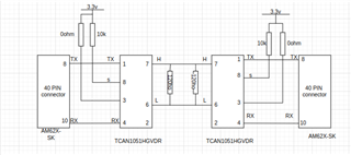
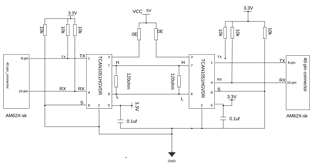
We have a CAN transceiver (TCAN1051HGVDR) which is externally connected to the 40 Pin connector. (Pin 8(E15) and Pin 10 (C15)).

We have made the connections as per the link below.

https://software-dl.ti.com/processor-sdk-linux/esd/AM62X/08_05_00_21/exports/docs/linux/How_to_Guides/Target/How_to_test_MCAN_on_AM62x.html#mcan-on-am62x

But the problem is after flashing the Am62x-base.wic Image to the SD Card, I can't able to see any Overlay (k3-am625-sk-mcan.dtbo) file in the root(root folder).

In the latest release of SDK ti-processor-sdk-linux-am62xx-evm-08.05.00.21-Linux-x86, we have Overlay file for CAN  in this path(arch/arm64/boot/dts/ti/k3-am625-sk-mcan.dts).

Do i need to convert this file to .dtbo and place it inside the root folder to test the CAN Interface. (Any procedure to convert the dts file to .dtbo).

or Do I need to include the k3-am625-sk-mcan.dts file inside the k3-am625-sk.dts file and create a dtb.  

kindly guide me through this, how to proceed the testing on CAN Interface.

Regards,

Murali Chikkanna

  • Hi TI,

    kindly can anyone guide me through the CAN inteface Testing on Am62x. We are struggling on this for a while.but cant able to find the solution.

    Regards,

    Murali C 

  • Hi Murali, 
    The overlay files/dtbos are not found in the standard wic image. You will need to build them by following certain commands in the PSDK linux source tree. After you build the overlay k3-am625-sk-mcan.dts file, you can copy it into the root partition for MCAN to work. 
    You can refer to the following article for detailed reference: 4.1.7. How to enable DT overlays on AM625 SK — Processor SDK AM62x Documentation

    Regards,
    Aparna

  • Hi Aparna,

    Thanks for the reply..

    I had build the overlay file, and copied the k3-am62x-sk-mcan.dtbo file into /root/boot.

    but when i tried to send data using cansend command the CAN bus goes to off state.

    i had setup two am62x sk board with two CAN transceivers.One act as Transmitter and the other act as Receiver.

    Transmitter side:

    ip link set can0 down.
    ip link set can0 type can bitrate 125000

    ip link set can 0 up

    cansend can0 123#DEADBEEF

    [ 170.474360] can: controller area network core
    [ 170.478830] NET: Registered protocol family 29
    [ 170.490795] can: raw protocol
    root@am62xx-evm:~# [ 170.498422] m_can_platform 20701000.can can0: bus-off

    Receiver Side:

    ip link set can0 down.
    ip link set can0 type can bitrate 125000

    ip link set can 0 up

    candump can0

    Kindly find the connection diagram below.

    We followed the below link to test can interface.

    https://software-dl.ti.com/processor-sdk-linux/esd/AM62X/08_05_00_21/exports/docs/linux/Foundational_Components/Kernel/Kernel_Drivers/MCAN.html

    kindly provide some solution to overcome this issue, we are struggling on this for almost 2 weeks.

    Regards

    Murali C

  • Murali,

    Please confirm that you also have pin 2 of the TCAN1051 connected to ground, and that you have the recommended 0.1uF decoupling capacitor between VCC and GND near the TCAN1051 XCVR.

    The other issue I see is that you have the pin 8 silent pin pulled high. This puts the transceiver in silent mode, meaning that the transmitter is disabled. This will definitely cause a bus-off state.

    Thanks,

    Stuart

  • Hi Stuart,

    Thanks for the reply, kindly find my response in blue below,

    Please confirm that you also have pin 2 of the TCAN1051 connected to ground, and that you have the recommended 0.1uF decoupling capacitor between VCC and GND near
    the TCAN1051 XCVR.

    Yes, we have connected pin 2 to ground and have a 0.uf capacitor between VCC and Gnd.

    The other issue I see is that you have the pin 8 silent pin pulled high. This puts the transceiver in silent mode, meaning that the transmitter is disabled.
    This will definitely cause a bus-off state.

    Yes, we have gone through the Datasheet and connected Pin 8 to ground, so that the transceiver will be in Normal mode.(Both Transmitter and Receiver Works).


    But still we can't able to get the output, we are still facing the same issue.

    Kindly find the updated block diagram for your reference.

    Regards,
    Murali C

  • Murali,

    Have you probed the CAN TX pins with a scope or logic analyzer to see if anything is present when you try to transmit? If you do see something, and can provide a logic analyzer plot, it may be helpful in diagnosing the issue.

    It might be useful to see a logic analyzer plot with both TX and RX lines simultaneously (four signals in total).

    Thanks,

    Stuart

  • Hi stuart,

    Sorry! for the late reply. yes we tried probing the TX pin using Logic Analyzer. we found some signals on that TX Pin. So we started debugging the transceiver connections, where we found a connection issue. After fixing that, MCAN Bus started working and we are able to send and receive Data.

    Thanks for the help.

    Regards,

    Murali Chikkanna 

  • Hi Stuart,
                  I am am facing similar issue, I have added mcan overlay on 'k3-am625-sk.dts. Here is my dts after adding mcan overlay:-

    // SPDX-License-Identifier: GPL-2.0
    /*
     * AM625 SK: https://www.ti.com/lit/zip/sprr448
     *
     * Copyright (C) 2021-2022 Texas Instruments Incorporated - https://www.ti.com/
     */
    
    /dts-v1/;
    
    #include <dt-bindings/leds/common.h>
    #include <dt-bindings/gpio/gpio.h>
    #include <dt-bindings/net/ti-dp83867.h>
    #include <dt-bindings/pinctrl/k3.h>
    #include <dt-bindings/interrupt-controller/irq.h>
    
    #include "k3-am625.dtsi"
    #include "k3-am62x-sk-common.dtsi"
    
    
    / {
            compatible =  "ti,am625-sk", "ti,am625";
        model = "Platform-AM625-SK-13mar2023";
    	transceiver1: can-phy0 {
                    compatible = "ti,tcan1042";
                    #phy-cells = <0>;
                    max-bitrate = <5000000>;
            };
    	wlan_lten: regulator-5 {
                    compatible = "regulator-fixed";
                    regulator-name = "wlan_lten";
                    regulator-min-microvolt = <3300000>;
                    regulator-max-microvolt = <3300000>;
                    regulator-always-on;
                    vin-supply = <&vcc_3v3_sys>;
                    gpios = <&exp1 11 GPIO_ACTIVE_LOW>;
            };
    
            wlan_en: regulator-6 {
                    /* OUTPUT of SN74AVC2T244DQMR */
                    compatible = "regulator-fixed";
                    regulator-name = "wlan_en";
                    regulator-min-microvolt = <1800000>;
                    regulator-max-microvolt = <1800000>;
                    enable-active-high;
                    vin-supply = <&wlan_lten>;
                    gpios = <&main_gpio0 71 GPIO_ACTIVE_HIGH>;
                    pinctrl-names = "default";
                    pinctrl-0 = <&wlan_en_pins_default>;
            };
    };
    
    &main_pmx0 {
            wlan_en_pins_default: wlan-en-pins-default {
                    pinctrl-single,pins = <
                            AM62X_IOPAD(0x124, PIN_OUTPUT, 7) /* (A23) MMC2_SDCD.GPIO0_71 */
                    >;
            };
    
            main_mmc2_pins_default: main-mmc2-pins-default {
                    pinctrl-single,pins = <
                            AM62X_IOPAD(0x120, PIN_INPUT, 0) /* (C24) MMC2_CMD */
                            AM62X_IOPAD(0x118, PIN_INPUT, 0) /* (D25) MMC2_CLK */
                            AM62X_IOPAD(0x114, PIN_INPUT, 0) /* (B24) MMC2_DAT0 */
                            AM62X_IOPAD(0x110, PIN_INPUT, 0) /* (C25) MMC2_DAT1 */
                            AM62X_IOPAD(0x10c, PIN_INPUT, 0) /* (E23) MMC2_DAT2 */
                            AM62X_IOPAD(0x108, PIN_INPUT, 0) /* (D24) MMC2_DAT3 */
                            AM62X_IOPAD(0x11c, PIN_INPUT, 0) /* (#N/A) MMC2_CLKB */
                    >;
            };
    
            main_wlirq_pins_default: main-wlirq-pins-default {
                    pinctrl-single,pins = <
                            AM62X_IOPAD(0x128, PIN_INPUT, 7) /* (B23) MMC2_SDWP.GPIO0_72 */
                    >;
            };
    
        main_spi2_pins_default: main-spi2-pins-default {
                    pinctrl-single,pins = <
                            AM62X_IOPAD(0x1B0, PIN_INPUT, 1)   /* (A20) SPI2_CLK pins  on expansion Header*/
                AM62X_IOPAD(0x1AC, PIN_OUTPUT, 1)  /* (E19) SPI2_CS0 pins on expansion Header */
                AM62X_IOPAD(0x194, PIN_INPUT, 1)   /* (B19) SPI2_D0 pins on expansion Header */
                AM62X_IOPAD(0x198, PIN_INPUT, 1)   /* (A19) SPI2_D1 pins on expansion Header */
                    >;
            };
    	main_mcan0_pins_default: main-mcan0-pins-default {
            pinctrl-single,pins = <
                AM62X_IOPAD(0x1dc, PIN_INPUT, 0)  /* (E15) MCAN0_RX */
                AM62X_IOPAD(0x1d8, PIN_OUTPUT, 0) /* (C15) MCAN0_TX */
            >;
        };
    };
    
    &main_i2c1 {
    	exp1: gpio@22 {
    		compatible = "ti,tca6424";
    		reg = <0x22>;
    		gpio-controller;
    		#gpio-cells = <2>;
    		gpio-line-names = "GPIO_CPSW2_RST", "GPIO_CPSW1_RST",
    				   "PRU_DETECT", "MMC1_SD_EN",
    				   "VPP_LDO_EN", "EXP_PS_3V3_En",
    				   "EXP_PS_5V0_En", "EXP_HAT_DETECT",
    				   "GPIO_AUD_RSTn", "GPIO_eMMC_RSTn",
    				   "UART1_FET_BUF_EN", "WL_LT_EN",
    				   "GPIO_HDMI_RSTn", "CSI_GPIO1",
    				   "CSI_GPIO2", "PRU_3V3_EN",
    				   "HDMI_INTn", "TEST_GPIO2",
    				   "MCASP1_FET_EN", "MCASP1_BUF_BT_EN",
    				   "MCASP1_FET_SEL", "UART1_FET_SEL",
    				   "TSINT#", "IO_EXP_TEST_LED";
    
    		interrupt-parent = <&main_gpio1>;
    		interrupts = <23 IRQ_TYPE_EDGE_FALLING>;
    		interrupt-controller;
    		#interrupt-cells = <2>;
    
    		pinctrl-names = "default";
    		pinctrl-0 = <&main_gpio1_ioexp_intr_pins_default>;
    	};
    };
    
    &sdhci2 {
    	vmmc-supply = <&wlan_en>;
    	pinctrl-names = "default";
    	pinctrl-0 = <&main_mmc2_pins_default>;
    	bus-width = <4>;
    	non-removable;
    	ti,fails-without-test-cd;
    	cap-power-off-card;
    	keep-power-in-suspend;
    	ti,driver-strength-ohm = <50>;
    	assigned-clocks = <&k3_clks 157 158>;
    	assigned-clock-parents = <&k3_clks 157 160>;
    
    	#address-cells = <1>;
    	#size-cells = <0>;
    	wlcore: wlcore@2 {
    		compatible = "ti,wl1837";
    		reg = <2>;
    		pinctrl-names = "default";
    		pinctrl-0 = <&main_wlirq_pins_default>;
    		interrupt-parent = <&main_gpio0>;
    		interrupts = <72 IRQ_TYPE_EDGE_FALLING>;
    	};
    };
    &main_mcan0 {
            status = "okay";
            pinctrl-names = "default";
            pinctrl-0 = <&main_mcan0_pins_default>;
            phys = <&transceiver1>;
    };
    &ospi0 {
    	flash@0 {
    		compatible = "jedec,spi-nor";
    		reg = <0x0>;
    		spi-tx-bus-width = <8>;
    		spi-rx-bus-width = <8>;
    		spi-max-frequency = <25000000>;
    		cdns,tshsl-ns = <60>;
    		cdns,tsd2d-ns = <60>;
    		cdns,tchsh-ns = <60>;
    		cdns,tslch-ns = <60>;
    		cdns,read-delay = <4>;
    		cdns,phy-mode;
    
    		partitions {
    			compatible = "fixed-partitions";
    			#address-cells = <1>;
    			#size-cells = <1>;
    
    			partition@0 {
    				label = "ospi.tiboot3";
    				reg = <0x0 0x80000>;
    			};
    
    			partition@80000 {
    				label = "ospi.tispl";
    				reg = <0x80000 0x200000>;
    			};
    
    			partition@280000 {
    				label = "ospi.u-boot";
    				reg = <0x280000 0x400000>;
    			};
    
    			partition@680000 {
    				label = "ospi.env";
    				reg = <0x680000 0x40000>;
    			};
    
    			partition@6c0000 {
    				label = "ospi.env.backup";
    				reg = <0x6c0000 0x40000>;
    			};
    
    			partition@800000 {
    				label = "ospi.rootfs";
    				reg = <0x800000 0x37c0000>;
    			};
    
    			partition@3fc0000 {
    				label = "ospi.phypattern";
    				reg = <0x3fc0000 0x40000>;
    			};
    		};
    	};
    };
    &main_spi2{
        pinctrl-names = "default";
     	pinctrl-0 = <&main_spi2_pins_default>;
        status = "okay";    
        adc@0 {
                compatible = "ti,adc128s052";
                reg = <0>;
                spi-max-frequency = <1000000>;
                #io-channel-cells = <1>;
            };
    };
    
    /*
    &main_i2c0 {
    	#address-cells = <1>;
    	#size-cells = <0>;
    
    	touchscreen@41 {
    		compatible = "ilitek,ili251x";
    		reg = <0x41>;
    		interrupt-parent = <&exp1>;
    		interrupts = <15 IRQ_TYPE_EDGE_FALLING>;
    		reset-gpios = <&exp2 18 GPIO_ACTIVE_LOW>;
    	};
    };
    */
    

    I can't test mcan after booting my image to sk-am62 evaluation board, however I stop boot on u-boot and use following command:-

    setenv name_overlays k3-am625-sk-mcan.dtbo
    boot

    Now I can test mcan successfully. Please confirm why mcan not coming by default with my changes.Thanks

  • Hello,

    In u-boot, can you try the saveenv command, like so:

    # setenv name_overlays k3-am625-sk-mcan.dtbo

    # saveenv

    # boot

    Then reboot the board to see if the overlay is applied.

  • Hi Mendez,
      yes after applying these command, its working. But please confirm how to do it with dts file

  • Hello, could you apply the following patch and rebuild?
    https://e2e.ti.com/cfs-file/__key/communityserver-discussions-components-files/791/0001_2D00_arm64_2D00_dts_2D00_ti_2D00_Enable_2D00_main_2D00_domain_2D00_MCAN_2D00_for_2D00_AM62x.patch

    Also another thing to watch for, in the u-boot environment, make sure boot_fit is set to 0. That way you are booting the dtb that is not in 'fitImage'. The difference between boot_fit set to 0 or 1 is that if boot_fit is set 0 zero, kernel 'Image' and the dtb will boot. If boot_fit is set to 1, the (kernel) 'fitImage' will be used instead.

  • Hi Mandez, I tried your patch. But it didn't solve my issue

  • Hello Tabish,

    To better help you, could you please explain what is not working? What are the symptoms? A console log could be useful and what is your physical setup?

  • I am using CAN module (TJA1050 - robu.in/product/tja1050-can-controller-bus-driver-interface-module/?gclid=EAIaIQobChMIooKRiMeU_gIVkn0rCh3rXwMTEAQYAyABEgLtzPD_BwE) with my sk-am62 evaluation board.

    I have connected J3 header pin number 8 with module Rx pin & pin number 10 with module Tx pin. I am providing power to the module with J24v header on my board. I am using PCAN tool (https://www.peak-system.com/PCAN-USB.199.0.html?&L=1)  to monitor signals. 

    To send the signal, I am referring this documents :- https://software-dl.ti.com/processor-sdk-linux/esd/AM64X/08_02_00_23/exports/docs/linux/Foundational_Components/Kernel/Kernel_Drivers/MCAN.html

    following are my commands:-

    ip link set can0 type can bitrate 1000000
    ip link set can0 up

    cansend can0 123#DEADBEEF

    I got nothing on PCAN.

    I also tried hardware self test by using following command:-

    ip link set can0 up type can bitrate 1000000 dbitrate 2000000 fd on loopback on
    candump can0 &
    cansend can0 300#AC.AB.AD.AE.75.49.AD.D1

    I got following result:-

    root@am62xx-lrd:~# ip link set can0 up type can bitrate 1000000 dbitrate 2000000 fd on loopback on
    [   80.746976] IPv6: ADDRCONF(NETDEV_CHANGE): can0: link becomes ready
    root@am62xx-lrd:~# candump can0 &
    [1] 1031
    interface = can0, family = 29, type = 3, proto = 1
    root@am62xx-lrd:~# [   96.514163] can: raw protocol
    
    root@am62xx-lrd:~# cansend can0 300#AC.AB.AD.AE.75.49.AD.D1
    interface = can0, family = 29, type = 3, proto = 1
    <0x001> [1] 2c 
    <0x001> [1] 2c

    Also, I observed that after connecting my module with J24, voltage gets drop to 1.1 V from 3.3 V. To cross check if module is faulty, I tried same setting with a different board, there is no voltage drop in that case, also CAN is working fine there.

  • Hello tabish,

    Could you try the following and show your results:

    # ip link set can0 type can bitrate 1000000
    # ip link set can0 up
    # cansend can0 123#DEADBEEF
    # ip -d -s link show can0
    # dmesg | grep can

    Thank you.

  • Hello Tabish,

    One problem you have is the power to the CAN transceiver: 'J24, voltage gets drop to 1.1 V from 3.3 V'. The CAN transceiver will not work with <2v VCC. Please get a reliable 3.3V or 5V and test again.

    regards,

    Judith