This thread has been locked.

If you have a related question, please click the "Ask a related question" button in the top right corner. The newly created question will be automatically linked to this question.

TDA4VM: Issues about using TI Surround Vision Calibration Tool when stitching surround vision images

Part Number: TDA4VM

Hi Team,

First, I refer to the official guidance document (link: https://software-dl.ti.com/jacinto7/esd/processor-sdk-rtos-jacinto7/08_05_00_11/exports/docs/vision_apps/docs/user_guide/PSDK_RTOS_UserGuide_3D_SurroundView_Manual_CalibTool.pdf)

The four surround-vision cameras on my side are placed on the front, rear, left, and right sides of the vehicle. According to the first step in the official document, cam1, cam2, cam3, and cam4 are the images obtained by the rear, front, right, and left cameras respectively. For the second step, I use the image center as Distortion point. In the third step, the focal length is set to 440 (this is obtained according to the image de-distortion effect in the tests), and I obtain the lut table and the LENS.BIN file. For the parameters in the fourth step, we zoom in eight times on the four corners of the vehicle and click in order the eight corner points, in the final test, the splicing result is very poor, as shown in the figure below:

Now we have a few questions:

1. Is it because the image placement in the first step is wrong, so cam1, cam2, cam3, and cam4 should be the data of which cameras respectively?

2. On the coordinate parameters of the fourth step (actually measured distance during calibration), we directly zoom in eight times. Is it okay? If not, could you specify how to set these coordinates or how to calibrate?

3. The splicing result is wrong, what are the reasons? Could you tell me how to correct it?

Kind regards,

Katherine

  • Hello Katherine,

    1. Cam1, cam2, cam3, cam4 are front, right, rear and left. I think it is a root cause.

    2. I never zoomed in when clicking corner points. So I am not sure if it is one of root cause. 

    Please fix 1 first, and see what you have.

    Best regards,

    Do-Kyoung

  • Hi Do-Kyoung,

    Thank you very much for your timely reply, but maybe my description is not clear enough, so there is a deviation in the second reply.

    On the coordinate parameters of the fourth step (actually measured distance during calibration), we directly zoom in eight times

    First of all,  the magnification of 8 times in the second question (a slip of the tongue, it should be 7 times) means that the coordinate values ​​​​of pattern-1, pattern-2, pattern-3, and pattern-4 are magnified by 7 times, because the size of our test vehicle is 4995*1910*1495mm in length, width and height, and the wheelbase is 2920mm, which is not feasible according to the size in the demo. (The pattern-width of the demo is 249, pattern-1, pattern-2, pattern -3, pattern-4 coordinates are (0,0), (0,867), (562,867), (562,0). Our pattern-width is 600, pattern-1, pattern-2, pattern-3, pattern- 4 are (0,0), (0,6069), (3934,6069), (3934,0))

    The relevant parameters of the demo are as follows.

    Our parameters are as follows.

    1. Cam1, cam2, cam3, cam4 are front, right, rear and left. I think it is a root cause.

    I changed Cam1, cam2, cam3, and cam4 to be front, right, back, and left respectively, but the results were not very satisfactory as shown in the figure below.

    Finally, I would like to attach four pictures of our front, right, back, and left, but I can't upload them perhaps due to the limited space in the 'reply' box.

    Best regards,

    Katherine

  • I don't understand this: 

    The pattern-width of the demo is 249, pattern-1, pattern-2, pattern -3, pattern-4 coordinates are (0,0), (0,867), (562,867), (562,0). Our pattern-width is 600, pattern-1, pattern-2, pattern-3, pattern- 4 are (0,0), (0,6069), (3934,6069), (3934,0). 


    My questions are:

    1. What's your actual pattern width and their positions? Calibration chart dimension should match to your pattern size and positions.

    2. Where are your cameras installed?

    3. Need to see captured images from front, left, rear and right cameras.

  • Hi Do-Kyoung,

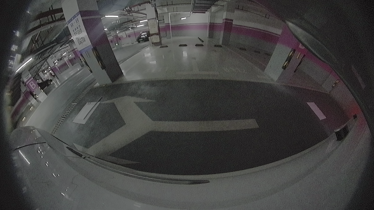
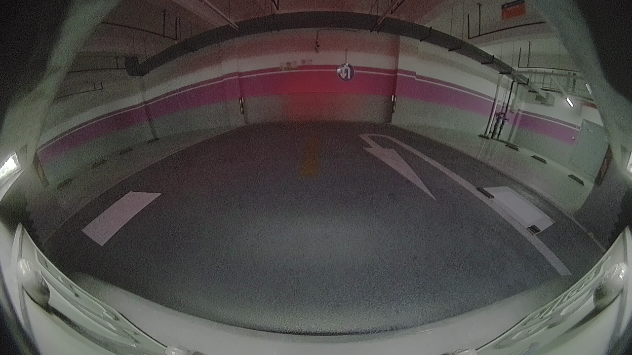
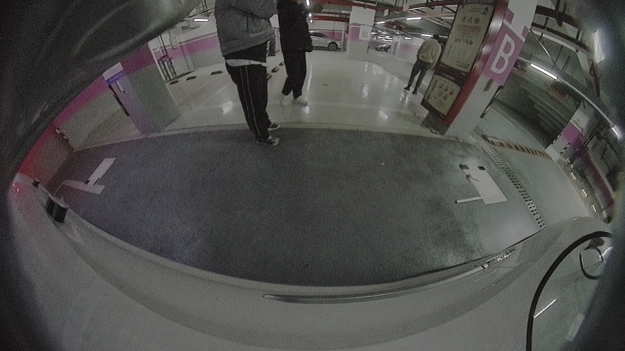
    I posted this question for a customer, and he uploaded his front, right, back, and left four pictures just know. They are as follows.

  • 1. What's your actual pattern width and their positions? Calibration chart dimension should match to your pattern size and positions.

    Sorry for the confusion. I'd like to clarify my previous description.

    The customer meant that the pattern width in TI's official demo is 249 (in mm), as shown in the first Figure 11 in my previous reply. And the positions of pattern-1, pattern-2, pattern -3, and pattern-4 in TI's official demo are (0,0), (0,867), (562,867), and (562,0) respectively as shown in the same picture.

    The customer's actual pattern width is 600 (in mm), as shown in the second Figure 11 in my previous reply. And the customer's actual positions of pattern-1, pattern-2, pattern -3, and pattern-4 are (0,0), (0,6069), (3934,6069), and (3934,0) respectively as shown in the same picture.

    For question 2, I will inquire the customer and get back to you as soon as he replies.

  • 2. Where are your cameras installed?

    The cameras are installed under the front bumper, rear bumper and left and right rearview mirrors of the vehicle respectively.

  • (Btw, the first and the second Figure 11 in your previous reply are identical)

    Then the customer should put 600, (0,0), (0,6069), (3934,6069), and (3934,0) in Figure 1.

  • Thanks for sharing images. I assume the customer is using white calibration charts. 

    I do not see any reason that calibration fails. First of all, please just make sure that they put correct (acutal) chart sizes in Figure 11 (in your previous reply). Chart size shouldn't be scaled or magnified depending on car size.

  • No. The size we enlarged refers to the new size obtained by zooming in 7 times based on the size of the demo. Then, we used this new size to place the cameras in the corresponding positions around the car to collect surround-vision image data. Therefore, the surround-vision images we collected are strictly matched with our related parameters.

  • Okay. What you are saying is that the chart parameters match to your chart position. (Zooming 7 times made me confused. As long as chart parameters match to actual chart placement, calibration should work). I do not see any reason that calibration failed. One thing you need to check is the order of control points (4 control points from each chart) when you click them.