This thread has been locked.

If you have a related question, please click the "Ask a related question" button in the top right corner. The newly created question will be automatically linked to this question.

PROCESSOR-SDK-AM64X: ENET open failure from R5 when A53 is running

Part Number: PROCESSOR-SDK-AM64X
Other Parts Discussed in Thread: TMDS64EVM, SYSCONFIG

Hi,

I'm working on AM64 EVM with SDK  08_02_00_31.

For UDP transmission and reception I'm working with the LWIP module according to your examples.

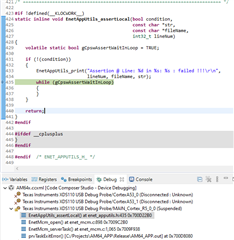
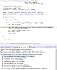
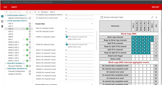
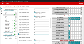
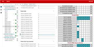
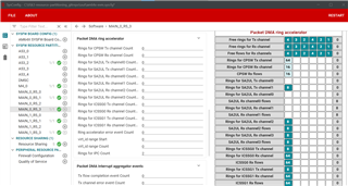
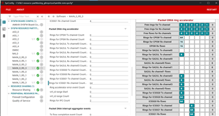
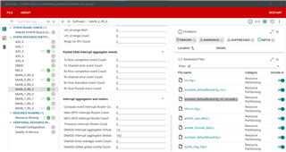
When I run it on R5 stand alone it runs properly but if I activate it when A53 is also running I get a failure from EnetMcm_open due to DMA open failure, printscreens attached.

I guess it related to the DTB file in the A53 which probably should disable any resource to let the R5 the ability to use it.

Please review it and advise.

Thanks,

Dekel

  • Hi Dekel,

    Thanks for your query.

    Can you please help me to get info about your setup and use case in more details ?

    1. you are working on SDK 8.2 correct ?

    • Can you move on latest SDK ?

    2. You are working on FreeRTOS. correct ?

    3. What/ which example  is running on A53 ?

    4. Which example you are running on R5F ?

    Please refer SDK release document for the supported features

    SDK 8.2: 

    SDK 8.5: 

    Best Regards

    Ashwani

  • Hi Ashwani,

    Regarding to the questions above:

    1.Currently I'm working on 8.2, maybe in the future I'll move to 8.5.

    2. Correct

    3. No example is running , it's an operational code which use some of your drivers and features .

    4. Same as 3

    Can you approve that LWIP usage in parallel on R5 and A53 is not working on SDK 8.2 but works on SDK 8.5?

    If not, please provide us a solution.

    Thanks,

    Dekel

  • Hello Dekel,

    I guess you're using Linux on A53, right? I believe you should check the board config that gets passed to SysFW.

    This is part of tiboot3.bin, and assigns resources to processors. When booting Linux via U-Boot that's different from MCU+ SDK via SBL.

    With U-Boot/Linux this is part of k3-image-gen.

    Regards,

    Dominic

  • Hi Ashwani,

    1. Are there any required changes in the linux device tree in order to run lwIP?

    I am trying to follow the documentation here:
    https://software-dl.ti.com/jacinto7/esd/processor-sdk-rtos-j7200/08_00_00_12/exports/docs/pdk_j7200_08_00_00_37/docs/userguide/j7200/modules/enet_lwip_userguide.html

    However since both A53 and R5F cores require DMA access, i was not sure if we need to make DTB changes to support DMA access by lwIP.

    Thank you,

    Ben S.

  • Hell Dekel,

    I suspect the problem is with the same DMA channels used in both R5F and A53 .That's why you can run the lwip examples when you run only the R5F examples but not when the A53 is running.

    As per the comments above I understand you want to run the lwip examples on the R5F when A53 is Running and then you can disable the TX and RX channels of DMA of lwip peripheral on the PROCESSOR SDK.

    Please use below link to change board cfg file and let me know if you have any problem.

    https://e2e.ti.com/support/processors-group/processors/f/processors-forum/1198105/faq-am64x-how-to-run-mcu-sdk-gpio_input_interrupt-example-for-r5fss0-0-with-linux-running-on-a53

    Regards,

    S.Anil. 

  • Hi Swargam,

    As Ben and I wrote above, the problem is about common usage of DMA channels.

    1. Regarding to the link you mentioned - in sciclient_defaultBoardcfg_rm_linux.c, which DMA channels should be assigned to the R5 and which channels to        the A53? are there additional required changes? please provide us a reference file of sciclient_defaultBoardcfg_rm_linux.c and other files if needed

    2. You wrote: "As per the comments above I understand you want to run the lwip examples on the R5F when A53 is Running and then you can disable the        TX and RX channels of DMA of lwip peripheral on the PROCESSOR SDK."

    Note that we're not working with your examples but with our operational code so the allocation is not temporary and we can't disable it as it's required for all the running. 

    Thanks,

    Dekel

  • Hell Dekel,

    Could you please share details about which example you are running?

    Regards,

    S.Anil.

  • Hello Dekel,

    Could you please update the changes below in your rm_cfg.c file and please use the FAQs above to compile and load the rm_cfg file.

    You can check the rm_cfg file from your processor SDK from below path.

    <INSTALL DIR>/board-support/k3-image-gen-2022.01/soc/am64x/evm/rm-cfg.c

    I don't know about PROCESSOR +SDK and Ethernet.

    So, please test and share the test results.

    /* Packet DMA CPSW Rx channel */
    {
    .start_resource = 16,
    .num_resource = 1,
    .type = RESASG_UTYPE (AM64X_DEV_DMASS0_PKTDMA_0,
    RESASG_SUBTYPE_PKTDMA_CPSW_RX_CHAN),
    .host_id = HOST_ID_A53_2,
    },
    {
    .start_resource = 16,
    .num_resource = 1,
    .type = RESASG_UTYPE (AM64X_DEV_DMASS0_PKTDMA_0,
    RESASG_SUBTYPE_PKTDMA_CPSW_RX_CHAN),
    .host_id = HOST_ID_MAIN_0_R5_1,
    },


    /* Packet DMA CPSW Tx channels */
    {
    .start_resource = 16,
    .num_resource = 8,
    .type = RESASG_UTYPE (AM64X_DEV_DMASS0_PKTDMA_0,
    RESASG_SUBTYPE_PKTDMA_CPSW_TX_CHAN),
    .host_id = HOST_ID_A53_2,
    },
    {
    .start_resource = 16,
    .num_resource = 8,
    .type = RESASG_UTYPE (AM64X_DEV_DMASS0_PKTDMA_0,
    RESASG_SUBTYPE_PKTDMA_CPSW_TX_CHAN),
    .host_id = HOST_ID_MAIN_0_R5_1,
    },


    /* Packet DMA CPSW Rx flows */
    {
    .start_resource = 16,
    .num_resource = 16,
    .type = RESASG_UTYPE (AM64X_DEV_DMASS0_PKTDMA_0,
    RESASG_SUBTYPE_PKTDMA_FLOW_CPSW_RX_CHAN),
    .host_id = HOST_ID_A53_2,
    },
    {
    .start_resource = 16,
    .num_resource = 16,
    .type = RESASG_UTYPE (AM64X_DEV_DMASS0_PKTDMA_0,
    RESASG_SUBTYPE_PKTDMA_FLOW_CPSW_RX_CHAN),
    .host_id = HOST_ID_MAIN_0_R5_1,
    },

    Regards,

    S.Anil

  • Hi Swargam,

    In the FAQs link you mentioned above written:

    "With the above changes, we have to then generate the updated Board Configuration binary file and then rebuild the Linux SBLs to reflect the changes."

    Please explain how to generate the board configuration binary file.

    Thanks,

    Dekel

  • Hello Dekel,

    After the above changes, build the sysfw-image & replace the tiboot3.bin on SD card with the updated tiboot3.bin image. 

    You can run the make sysfw-image command. So, your board configuration binaries are updated according to the above changes and next the tiboot3.bin file is updated.

    You can refer below link for compilation steps for rm-cfg.c file on processor SDK side.

    https://e2e.ti.com/support/processors-group/processors/f/processors-forum/1181741/am6442-how-r5-core-boot-as-processor-linux-sdk-then-load-mcu-plus-sdk-ccs-r5-demo/4490754#4490754

    Regards,

    S.Anil.

  • Hi Swargam,

    You wrote:

    "You can run the make sysfw-image command. So, your board configuration binaries are updated according to the above changes and next the tiboot3.bin file is updated."

    Please specify the path to the command file (I didn't find such a file name or similiar) and explain how to run it.

    Thanks,

    Dekel

  • Hi Dekel,

    Please once confirm the boot flow you are using. Are you using SBL from MCU+ SDK to load and run Linux on A53? Or are you using tiboot3.bin from Processor SDK to load and run Linux.

    Regards,

    Prashant

  • Hi Prashant,

    We use EMMC boot.

    Our secondary bootloader calls the applications of all the R5 processors and the u-boot of the A53.

    Currently we use R5_0_0 only and the A53 starts up when R5 is already running.

    The makefile of the secondary bootloader includes all the required steps so the ROM bootloader can validate it.

    The makefile includes as well the board configuration BIN.

    #
    # Auto generated makefile - DO NOT MODIFY
    #
    
    # Below variables need to be defined outside this file or via command line
    # - MCU_PLUS_SDK_PATH
    # - PROFILE
    # - CG_TOOL_ROOT
    # - OUTNAME
    # - CCS_INSTALL_DIR
    # - CCS_IDE_MODE
    
    CCS_PATH=$(CCS_INSTALL_DIR)
    include $(MCU_PLUS_SDK_PATH)/imports.mak
    include $(MCU_PLUS_SDK_PATH)/devconfig/devconfig.mak
    
    STRIP=$(CG_TOOL_ROOT)/bin/tiarmstrip
    OBJCOPY=$(CG_TOOL_ROOT)/bin/tiarmobjcopy
    ifeq ($(OS), Windows_NT)
    	PYTHON=python
    else
    	PYTHON=python3
    endif
    
    OUTFILE=$(PROFILE)/$(OUTNAME).out
    BOOTIMAGE_PATH=$(abspath ${PROFILE})
    BOOTIMAGE_NAME_GP:=$(BOOTIMAGE_PATH)/$(OUTNAME).tiimage
    BOOTIMAGE_NAME_HS:=sbl_emmc_linux.$(PROFILE).hs.tiimage
    ifeq ($(DEVICE_TYPE),HS)
    	BOOTIMAGE_NAME=$(BOOTIMAGE_NAME_HS)
    else
    	BOOTIMAGE_NAME=$(BOOTIMAGE_NAME_GP)
    endif
    BOOTIMAGE_BIN_NAME:=$(BOOTIMAGE_PATH)/$(OUTNAME).bin
    
    #
    # Generation of boot image which can be loaded by ROM Boot Loader (RBL)
    #
    ifeq ($(OS),Windows_NT)
    EXE_EXT=.exe
    endif
    ifeq ($(OS),Windows_NT)
      BOOTIMAGE_CERT_GEN_CMD=powershell -executionpolicy unrestricted -command $(MCU_PLUS_SDK_PATH)/tools/boot/signing/x509CertificateGen.ps1
    else
      BOOTIMAGE_CERT_GEN_CMD=$(MCU_PLUS_SDK_PATH)/tools/boot/signing/x509CertificateGen.sh
    endif
    BOOTIMAGE_TEMP_OUT_FILE=$(PROFILE)/temp_stdout_$(PROFILE).txt
    
    BOOTIMAGE_CERT_KEY=$(APP_SIGNING_KEY)
    BOOTIMAGE_CERT_GEN_CMD=$(PYTHON) $(MCU_PLUS_SDK_PATH)/tools/boot/signing/rom_image_gen.py
    SYSFW_PATH=$(MCU_PLUS_SDK_PATH)/source/drivers/sciclient/soc/am64x_am243x
    SYSFW_LOAD_ADDR=0x44000
    BOARDCFG_LOAD_ADDR=0x7B000
    BOARDCFG_BLOB=$(MCU_PLUS_SDK_PATH)/source/drivers/sciclient/sciclient_default_boardcfg/am64x_am243x/boardcfg_blob_linux.bin
    
    OBJCOPY=$(CCS_PATH)/utils/tiobj2bin/tiobj2bin
    
    SBL_RUN_ADDRESS=0x70000000
    
    SBL_PREBUILT_PATH=$(MCU_PLUS_SDK_PATH)/tools/boot/sbl_prebuilt/am64x-evm
    
    all:
    ifeq ($(CCS_IDE_MODE),cloud)
    #	No post build steps
    else
    	@echo  Boot image: am64x:r5fss0-0:nortos:ti-arm-clang $(BOOTIMAGE_NAME) ...
    	$(OBJCOPY) $(OUTFILE) $(BOOTIMAGE_BIN_NAME) $(CGT_TI_ARM_CLANG_PATH)/bin/tiarmofd $(CGT_TI_ARM_CLANG_PATH)/bin/tiarmhex $(CCS_PATH)/utils/tiobj2bin/mkhex4bin
    ifeq ($(DEVICE_TYPE),HS)
    	$(BOOTIMAGE_CERT_GEN_CMD) --swrv 1 --sbl-bin $(BOOTIMAGE_BIN_NAME) --sysfw-bin $(SYSFW_PATH)/sysfw-hs-enc.bin --sysfw-inner-cert $(SYSFW_PATH)/sysfw-hs-enc-cert.bin --boardcfg-blob $(BOARDCFG_BLOB) --sbl-loadaddr $(SBL_RUN_ADDRESS) --sysfw-loadaddr $(SYSFW_LOAD_ADDR) --bcfg-loadaddr $(BOARDCFG_LOAD_ADDR) --key $(BOOTIMAGE_CERT_KEY) --debug DBG_FULL_ENABLE --rom-image $(BOOTIMAGE_NAME)
    else
    	$(BOOTIMAGE_CERT_GEN_CMD) --swrv 1 --sbl-bin $(BOOTIMAGE_BIN_NAME) --sysfw-bin $(SYSFW_PATH)/sysfw.bin --boardcfg-blob $(BOARDCFG_BLOB) --sbl-loadaddr $(SBL_RUN_ADDRESS) --sysfw-loadaddr $(SYSFW_LOAD_ADDR) --bcfg-loadaddr $(BOARDCFG_LOAD_ADDR) --key $(BOOTIMAGE_CERT_KEY) --rom-image $(BOOTIMAGE_NAME)
    endif
    	$(COPY) $(BOOTIMAGE_NAME) $(BOOTIMAGE_PATH)/tiboot3.bin
    	@echo  Boot image: am64x:r5fss0-0:nortos:ti-arm-clang $(BOOTIMAGE_NAME) Done !!!
    	@echo  .
    endif
    

    Let me know if additional information is needed.

    Thanks,

    Dekel  

  • Hi Dekel,

    We took this as a test gap on our side.

    You are trying this on AM64x-evm. correct ?

    No example is running , it's an operational code which use some of your drivers and features .

    As I do not have your complete code to run on my setup.

    Help me with steps I can follow to recreate issue on my side (preferably: start with existing LWIP examples on AM64x-evm using SDK 8.5) ?

    Best Regards

    Ashwani

  • Hi Ashwani,

    For LWIP I'm using enet_lwip_icssg example and for RP messages I'm using ipc_rpmsg_echo_linux example.

    The board is AM64x-evm.

    Thanks,

    Dekel

  • Thanks Dekel,

    I am following below steps to reproduce the issue:

    Assumption:

    • R5F (RTOS) and A53 (Linux) both are not trying to access ICSSG as this is not a supported feature in SDK.
    • R5F (RTOS) and A53 (Linux) both are not trying to access CPSW as this is not a supported feature in SDK.

    Using baselinehttps://www.ti.com/tool/download/MCU-PLUS-SDK-AM64X/08.02.00.31

    1. Start "enet_lwip_icssg example" on R5F_0_0 to starts communication with ICSGG port. 
      1. Then start "ipc_rpmsg_echo_linux" on A53
      2. Should get "a failure from EnetMcm_open due to DMA open failure"

    or

    1. start "ipc_rpmsg_echo_linux" on A53
      1. Then, start "enet_lwip_icssg example" on R5F_0_0 to starts communication with ICSGG port. 
      2. Should get "a failure from EnetMcm_open due to DMA open failure"

    Note: We have fixes for DMA channels sharing (among cores) related issue in SDK 8.3 and onwards. So, It will be a help you can try SDK 8.5 on your side.

    Best Regards

    Ashwani

  • Hi Ashwani,

    Can yoy approve that if you're running the same scenario on SDK 8.5 then you have no failures?

    Thanks,

    Dekel

  • Can yoy approve that if you're running the same scenario on SDK 8.5 then you have no failures?

    First please approve that you are following below assumption otherwise no use of trying anything on my side.

    Then, I will start with SDK 8.2

    If issues are reproduce, I will confirm it.

    Then same steps on SDK 8.5 and update you.

    • R5F (RTOS) and A53 (Linux) both are not trying to access ICSSG as this is not a supported feature in SDK.
    • R5F (RTOS) and A53 (Linux) both are not trying to access CPSW as this is not a supported feature in SDK.

    For now, I can confirm these assumptions for SDK 8.5 as well.

    Best Regards

    Ashwani

  • Hi Ashwani,

    I will attach the DTS file we are using in Linux.
    We were helped by to create this DTS in this thread

    // SPDX-License-Identifier: GPL-2.0
    /*
     * Copyright (C) 2020-2021 Texas Instruments Incorporated - https://www.ti.com/
     */
    
    /dts-v1/;
    
    #include <dt-bindings/phy/phy.h>
    #include <dt-bindings/mux/ti-serdes.h>
    #include <dt-bindings/leds/common.h>
    #include <dt-bindings/gpio/gpio.h>
    #include <dt-bindings/net/ti-dp83867.h>
    #include "k3-am642.dtsi"
    
    / {
            compatible =  "ti,am642-evm", "ti,am642";
            model = "Texas Instruments AM642 EVM";
    
            chosen {
                    stdout-path = "serial2:115200n8";
                    bootargs = "console=ttyS2,115200n8 earlycon=ns16550a,mmio32,0x02800000";
            };
    
            memory@80000000 {
                    device_type = "memory";
                    /* 2G RAM */
                    reg = <0x00000000 0x80000000 0x00000000 0x80000000>;
    
            };
    
            reserved-memory {
                    #address-cells = <2>;
                    #size-cells = <2>;
                    ranges;
    
                    secure_ddr: optee@9e800000 {
                            reg = <0x00 0x9e800000 0x00 0x01800000>; /* for OP-TEE */
                            alignment = <0x1000>;
                            no-map;
                    };
    
                    main_r5fss0_core0_dma_memory_region: r5f-dma-memory@a0000000 {
                            compatible = "shared-dma-pool";
                            reg = <0x00 0xa0000000 0x00 0x100000>;
                            no-map;
                    };
    
                    main_r5fss0_core0_memory_region: r5f-memory@a0100000 {
                            compatible = "shared-dma-pool";
                            reg = <0x00 0xa0100000 0x00 0xf00000>;
                            no-map;
                    };
    
                    main_r5fss0_core1_dma_memory_region: r5f-dma-memory@a1000000 {
                            compatible = "shared-dma-pool";
                            reg = <0x00 0xa1000000 0x00 0x100000>;
                            no-map;
                    };
    
                    main_r5fss0_core1_memory_region: r5f-memory@a1100000 {
                            compatible = "shared-dma-pool";
                            reg = <0x00 0xa1100000 0x00 0xf00000>;
                            no-map;
                    };
    
                    main_r5fss1_core0_dma_memory_region: r5f-dma-memory@a2000000 {
                            compatible = "shared-dma-pool";
                            reg = <0x00 0xa2000000 0x00 0x100000>;
                            no-map;
                    };
    
                    main_r5fss1_core0_memory_region: r5f-memory@a2100000 {
                            compatible = "shared-dma-pool";
                            reg = <0x00 0xa2100000 0x00 0xf00000>;
                            no-map;
                    };
    
                    main_r5fss1_core1_dma_memory_region: r5f-dma-memory@a3000000 {
                            compatible = "shared-dma-pool";
                            reg = <0x00 0xa3000000 0x00 0x100000>;
                            no-map;
                    };
    
                    main_r5fss1_core1_memory_region: r5f-memory@a3100000 {
                            compatible = "shared-dma-pool";
                            reg = <0x00 0xa3100000 0x00 0xf00000>;
                            no-map;
                    };
    
                    mcu_m4fss_dma_memory_region: m4f-dma-memory@a4000000 {
                            compatible = "shared-dma-pool";
                            reg = <0x00 0xa4000000 0x00 0x100000>;
                            no-map;
                    };
    
                    mcu_m4fss_memory_region: m4f-memory@a4100000 {
                            compatible = "shared-dma-pool";
                            reg = <0x00 0xa4100000 0x00 0xf00000>;
                            no-map;
                    };
    
                    rtos_ipc_memory_region: ipc-memories@a5000000 {
                            reg = <0x00 0xa5000000 0x00 0x00800000>;
                            alignment = <0x1000>;
                            no-map;
                    };
            };
    
            evm_12v0: fixedregulator-evm12v0 {
                    /* main DC jack */
                    compatible = "regulator-fixed";
                    regulator-name = "evm_12v0";
                    regulator-min-microvolt = <12000000>;
                    regulator-max-microvolt = <12000000>;
                    regulator-always-on;
                    regulator-boot-on;
            };
    
            vsys_5v0: fixedregulator-vsys5v0 {
                    /* output of LM5140 */
                    compatible = "regulator-fixed";
                    regulator-name = "vsys_5v0";
                    regulator-min-microvolt = <5000000>;
                    regulator-max-microvolt = <5000000>;
                    vin-supply = <&evm_12v0>;
                    regulator-always-on;
                    regulator-boot-on;
            };
    
            vsys_3v3: fixedregulator-vsys3v3 {
                    /* output of LM5140 */
                    compatible = "regulator-fixed";
                    regulator-name = "vsys_3v3";
                    regulator-min-microvolt = <3300000>;
                    regulator-max-microvolt = <3300000>;
                    vin-supply = <&evm_12v0>;
                    regulator-always-on;
                    regulator-boot-on;
            };
    
            vdd_mmc1: fixed-regulator-sd {
                    /* TPS2051BD */
                    compatible = "regulator-fixed";
                    regulator-name = "vdd_mmc1";
                    regulator-min-microvolt = <3300000>;
                    regulator-max-microvolt = <3300000>;
                    regulator-boot-on;
                    enable-active-high;
                    vin-supply = <&vsys_3v3>;
                    gpio = <&exp1 6 GPIO_ACTIVE_HIGH>;
            };
    
            vddb: fixedregulator-vddb {
                    compatible = "regulator-fixed";
                    regulator-name = "vddb_3v3_display";
                    regulator-min-microvolt = <3300000>;
                    regulator-max-microvolt = <3300000>;
                    vin-supply = <&vsys_3v3>;
                    regulator-always-on;
                    regulator-boot-on;
            };
    
            leds {
                    compatible = "gpio-leds";
    
                    led-0 {
                            label = "am64-evm:red:heartbeat";
                            gpios = <&exp1 16 GPIO_ACTIVE_HIGH>;
                            linux,default-trigger = "heartbeat";
                            function = LED_FUNCTION_HEARTBEAT;
                            default-state = "off";
                    };
            };
    
            mdio_mux: mux-controller {
                    compatible = "gpio-mux";
                    #mux-control-cells = <0>;
    
                    mux-gpios = <&exp1 12 GPIO_ACTIVE_HIGH>;
            };
    
            mdio_mux_1: mdio-mux-1 {
                    compatible = "mdio-mux-multiplexer";
                    mux-controls = <&mdio_mux>;
                    mdio-parent-bus = <&cpsw3g_mdio>;
                    #address-cells = <1>;
                    #size-cells = <0>;
    
                    mdio@1 {
                            reg = <0x1>;
                            #address-cells = <1>;
                            #size-cells = <0>;
    
                            cpsw3g_phy3: ethernet-phy@3 {
                                    reg = <3>;
                            };
                    };
            };
    
            transceiver1: can-phy0 {
                    compatible = "ti,tcan1042";
                    #phy-cells = <0>;
                    max-bitrate = <5000000>;
                    standby-gpios = <&exp1 8 GPIO_ACTIVE_HIGH>;
            };
    
            transceiver2: can-phy1 {
                    compatible = "ti,tcan1042";
                    #phy-cells = <0>;
                    max-bitrate = <5000000>;
                    standby-gpios = <&exp1 9 GPIO_ACTIVE_HIGH>;
            };
    
            icssg1_eth: icssg1-eth {
                    status = "disabled";
            };
    };
    
    &main_r5fss0_core0 {
            mboxes = <&mailbox0_cluster2 &mbox_main_r5fss0_core0>;
            memory-region = <&main_r5fss0_core0_dma_memory_region>,
                            <&main_r5fss0_core0_memory_region>;
            sram = <&main_r5fss0_core0_sram>;
    };
    
    &main_r5fss0_core1 {
            mboxes = <&mailbox0_cluster2 &mbox_main_r5fss0_core1>;
            memory-region = <&main_r5fss0_core1_dma_memory_region>,
                            <&main_r5fss0_core1_memory_region>;
    //      sram = <&main_r5fss0_core1_sram>;
    };
    
    &main_r5fss1_core0 {
            mboxes = <&mailbox0_cluster4 &mbox_main_r5fss1_core0>;
            memory-region = <&main_r5fss1_core0_dma_memory_region>,
                            <&main_r5fss1_core0_memory_region>;
    //      sram = <&main_r5fss1_core0_sram>;
    };
    
    &main_r5fss1_core1 {
            mboxes = <&mailbox0_cluster4 &mbox_main_r5fss1_core1>;
            memory-region = <&main_r5fss1_core1_dma_memory_region>,
                            <&main_r5fss1_core1_memory_region>;
    //      sram = <&main_r5fss1_core1_sram>;
    };
    
    &mcu_m4fss {
            mboxes = <&mailbox0_cluster6 &mbox_m4_0>;
            memory-region = <&mcu_m4fss_dma_memory_region>,
                            <&mcu_m4fss_memory_region>;
    };
    
    &main_pmx0 {
            main_mmc1_pins_default: main-mmc1-pins-default {
                    pinctrl-single,pins = <
                            AM64X_IOPAD(0x0294, PIN_INPUT_PULLUP, 0) /* (J19) MMC1_CMD */
                            AM64X_IOPAD(0x028c, PIN_INPUT_PULLDOWN, 0) /* (L20) MMC1_CLK */
                            AM64X_IOPAD(0x0288, PIN_INPUT_PULLUP, 0) /* (K21) MMC1_DAT0 */
                            AM64X_IOPAD(0x0284, PIN_INPUT_PULLUP, 0) /* (L21) MMC1_DAT1 */
                            AM64X_IOPAD(0x0280, PIN_INPUT_PULLUP, 0) /* (K19) MMC1_DAT2 */
                            AM64X_IOPAD(0x027c, PIN_INPUT_PULLUP, 0) /* (K18) MMC1_DAT3 */
                            AM64X_IOPAD(0x0298, PIN_INPUT_PULLUP, 0) /* (D19) MMC1_SDCD */
                            AM64X_IOPAD(0x029c, PIN_INPUT, 0) /* (C20) MMC1_SDWP */
                            AM64X_IOPAD(0x0290, PIN_INPUT, 0) /* MMC1_CLKLB */
                    >;
            };
    
            main_uart0_pins_default: main-uart0-pins-default {
                    pinctrl-single,pins = <
                            AM64X_IOPAD(0x0238, PIN_INPUT, 0) /* (B16) UART0_CTSn */
                            AM64X_IOPAD(0x023c, PIN_OUTPUT, 0) /* (A16) UART0_RTSn */
                            AM64X_IOPAD(0x0230, PIN_INPUT, 0) /* (D15) UART0_RXD */
                            AM64X_IOPAD(0x0234, PIN_OUTPUT, 0) /* (C16) UART0_TXD */
                    >;
            };
    
            main_spi0_pins_default: main-spi0-pins-default {
                    pinctrl-single,pins = <
                            AM64X_IOPAD(0x0210, PIN_INPUT, 0) /* (D13) SPI0_CLK */
                            AM64X_IOPAD(0x0208, PIN_OUTPUT, 0) /* (D12) SPI0_CS0 */
                            AM64X_IOPAD(0x0214, PIN_OUTPUT, 0) /* (A13) SPI0_D0 */
                            AM64X_IOPAD(0x0218, PIN_INPUT, 0) /* (A14) SPI0_D1 */
                    >;
            };
    
            main_i2c1_pins_default: main-i2c1-pins-default {
                    pinctrl-single,pins = <
                            AM64X_IOPAD(0x0268, PIN_INPUT_PULLUP, 0) /* (C18) I2C1_SCL */
                            AM64X_IOPAD(0x026c, PIN_INPUT_PULLUP, 0) /* (B19) I2C1_SDA */
                    >;
            };
    
            mdio1_pins_default: mdio1-pins-default {
                    pinctrl-single,pins = <
                            AM64X_IOPAD(0x01fc, PIN_OUTPUT, 4) /* (R2) PRG0_PRU1_GPO19.MDIO0_MDC */
                            AM64X_IOPAD(0x01f8, PIN_INPUT, 4) /* (P5) PRG0_PRU1_GPO18.MDIO0_MDIO */
                    >;
            };
    
            rgmii1_pins_default: rgmii1-pins-default {
                    pinctrl-single,pins = <
                            AM64X_IOPAD(0x01cc, PIN_INPUT, 4) /* (W5) PRG0_PRU1_GPO7.RGMII1_RD0 */
                            AM64X_IOPAD(0x01d4, PIN_INPUT, 4) /* (Y5) PRG0_PRU1_GPO9.RGMII1_RD1 */
                            AM64X_IOPAD(0x01d8, PIN_INPUT, 4) /* (V6) PRG0_PRU1_GPO10.RGMII1_RD2 */
                            AM64X_IOPAD(0x01f4, PIN_INPUT, 4) /* (V5) PRG0_PRU1_GPO17.RGMII1_RD3 */
                            AM64X_IOPAD(0x0188, PIN_INPUT, 4) /* (AA5) PRG0_PRU0_GPO10.RGMII1_RXC */
                            AM64X_IOPAD(0x0184, PIN_INPUT, 4) /* (W6) PRG0_PRU0_GPO9.RGMII1_RX_CTL */
                            AM64X_IOPAD(0x0124, PIN_OUTPUT, 4) /* (V15) PRG1_PRU1_GPO7.RGMII1_TD0 */
                            AM64X_IOPAD(0x012c, PIN_OUTPUT, 4) /* (V14) PRG1_PRU1_GPO9.RGMII1_TD1 */
                            AM64X_IOPAD(0x0130, PIN_OUTPUT, 4) /* (W14) PRG1_PRU1_GPO10.RGMII1_TD2 */
                            AM64X_IOPAD(0x014c, PIN_OUTPUT, 4) /* (AA14) PRG1_PRU1_GPO17.RGMII1_TD3 */
                            AM64X_IOPAD(0x00e0, PIN_OUTPUT, 4) /* (U14) PRG1_PRU0_GPO10.RGMII1_TXC */
                            AM64X_IOPAD(0x00dc, PIN_OUTPUT, 4) /* (U15) PRG1_PRU0_GPO9.RGMII1_TX_CTL */
                    >;
            };
    
           rgmii2_pins_default: rgmii2-pins-default {
                    pinctrl-single,pins = <
                            AM64X_IOPAD(0x0108, PIN_INPUT, 4) /* (W11) PRG1_PRU1_GPO0.RGMII2_RD0 */
                            AM64X_IOPAD(0x010c, PIN_INPUT, 4) /* (V11) PRG1_PRU1_GPO1.RGMII2_RD1 */
                            AM64X_IOPAD(0x0110, PIN_INPUT, 4) /* (AA12) PRG1_PRU1_GPO2.RGMII2_RD2 */
                            AM64X_IOPAD(0x0114, PIN_INPUT, 4) /* (Y12) PRG1_PRU1_GPO3.RGMII2_RD3 */
                            AM64X_IOPAD(0x0120, PIN_INPUT, 4) /* (U11) PRG1_PRU1_GPO6.RGMII2_RXC */
                            AM64X_IOPAD(0x0118, PIN_INPUT, 4) /* (W12) PRG1_PRU1_GPO4.RGMII2_RX_CTL */
                            AM64X_IOPAD(0x0134, PIN_OUTPUT, 4) /* (AA10) PRG1_PRU1_GPO11.RGMII2_TD0 */
                            AM64X_IOPAD(0x0138, PIN_OUTPUT, 4) /* (V10) PRG1_PRU1_GPO12.RGMII2_TD1 */
                            AM64X_IOPAD(0x013c, PIN_OUTPUT, 4) /* (U10) PRG1_PRU1_GPO13.RGMII2_TD2 */
                            AM64X_IOPAD(0x0140, PIN_OUTPUT, 4) /* (AA11) PRG1_PRU1_GPO14.RGMII2_TD3 */
                            AM64X_IOPAD(0x0148, PIN_OUTPUT, 4) /* (Y10) PRG1_PRU1_GPO16.RGMII2_TXC */
                            AM64X_IOPAD(0x0144, PIN_OUTPUT, 4) /* (Y11) PRG1_PRU1_GPO15.RGMII2_TX_CTL */
                    >;
            };
    
            main_usb0_pins_default: main-usb0-pins-default {
                    pinctrl-single,pins = <
                            AM64X_IOPAD(0x02a8, PIN_OUTPUT, 0) /* (E19) USB0_DRVVBUS */
                    >;
            };
    
            main_mcan0_pins_default: main-mcan0-pins-default {
                    pinctrl-single,pins = <
                            AM64X_IOPAD(0x0254, PIN_INPUT, 0) /* (B17) MCAN0_RX */
                            AM64X_IOPAD(0x0250, PIN_OUTPUT, 0) /* (A17) MCAN0_TX */
                    >;
            };
    
            main_mcan1_pins_default: main-mcan1-pins-default {
                    pinctrl-single,pins = <
                            AM64X_IOPAD(0x025c, PIN_INPUT, 0) /* (D17) MCAN1_RX */
                            AM64X_IOPAD(0x0258, PIN_OUTPUT, 0) /* (C17) MCAN1_TX */
                    >;
            };
    
            icssg1_rgmii1_pins_default: icssg1-rgmii1-pins-default {
                    pinctrl-single,pins = <
                            AM64X_IOPAD(0x00b8, PIN_INPUT, 2) /* (Y7) PRG1_PRU0_GPO0.PRG1_RGMII1_RD0 */
                            AM64X_IOPAD(0x00bc, PIN_INPUT, 2) /* (U8) PRG1_PRU0_GPO1.PRG1_RGMII1_RD1 */
                            AM64X_IOPAD(0x00c0, PIN_INPUT, 2) /* (W8) PRG1_PRU0_GPO2.PRG1_RGMII1_RD2 */
                            AM64X_IOPAD(0x00c4, PIN_INPUT, 2) /* (V8) PRG1_PRU0_GPO3.PRG1_RGMII1_RD3 */
                            AM64X_IOPAD(0x00d0, PIN_INPUT, 2) /* (AA7) PRG1_PRU0_GPO6.PRG1_RGMII1_RXC */
                            AM64X_IOPAD(0x00c8, PIN_INPUT, 2) /* (Y8) PRG1_PRU0_GPO4.PRG1_RGMII1_RX_CTL */
                            AM64X_IOPAD(0x00e4, PIN_INPUT, 2) /* (AA8) PRG1_PRU0_GPO11.PRG1_RGMII1_TD0 */
                            AM64X_IOPAD(0x00e8, PIN_INPUT, 2) /* (U9) PRG1_PRU0_GPO12.PRG1_RGMII1_TD1 */
                            AM64X_IOPAD(0x00ec, PIN_INPUT, 2) /* (W9) PRG1_PRU0_GPO13.PRG1_RGMII1_TD2 */
                            AM64X_IOPAD(0x00f0, PIN_INPUT, 2) /* (AA9) PRG1_PRU0_GPO14.PRG1_RGMII1_TD3 */
                            AM64X_IOPAD(0x00f8, PIN_INPUT, 2) /* (V9) PRG1_PRU0_GPO16.PRG1_RGMII1_TXC */
                            AM64X_IOPAD(0x00f4, PIN_INPUT, 2) /* (Y9) PRG1_PRU0_GPO15.PRG1_RGMII1_TX_CTL */
                    >;
            };
    
            main_ecap0_pins_default: main-ecap0-pins-default {
                    pinctrl-single,pins = <
                            AM64X_IOPAD(0x0270, PIN_INPUT, 0) /* (D18) ECAP0_IN_APWM_OUT */
                    >;
            };
    };
    
    &main_uart0 {
            pinctrl-names = "default";
            pinctrl-0 = <&main_uart0_pins_default>;
    };
    
    /* main_uart1 is reserved for firmware usage */
    &main_uart1 {
            status = "reserved";
    };
    
    &main_uart2 {
            status = "disabled";
    };
    
    &main_uart3 {
            status = "disabled";
    };
    
    &main_uart4 {
            status = "disabled";
    };
    
    &main_uart5 {
            status = "disabled";
    };
    
    &main_uart6 {
            status = "disabled";
    };
    
    &mcu_uart0 {
            status = "disabled";
    };
    
    &mcu_uart1 {
            status = "disabled";
    };
    
    &main_i2c1 {
            pinctrl-names = "default";
            pinctrl-0 = <&main_i2c1_pins_default>;
            clock-frequency = <400000>;
    
            exp1: gpio@22 {
                    compatible = "ti,tca6424";
                    reg = <0x22>;
                    gpio-controller;
                    #gpio-cells = <2>;
                    gpio-line-names = "GPIO_eMMC_RSTn", "CAN_MUX_SEL",
                                      "GPIO_CPSW1_RST", "GPIO_RGMII1_RST",
                                      "GPIO_RGMII2_RST", "GPIO_PCIe_RST_OUT",
                                      "MMC1_SD_EN", "FSI_FET_SEL",
                                      "MCAN0_STB_3V3", "MCAN1_STB_3V3",
                                      "CPSW_FET_SEL", "CPSW_FET2_SEL",
                                      "PRG1_RGMII2_FET_SEL", "TEST_GPIO2",
                                      "GPIO_OLED_RESETn", "VPP_LDO_EN",
                                      "TEST_LED1", "TP92", "TP90", "TP88",
                                      "TP87", "TP86", "TP89", "TP91";
            };
    
            /* osd9616p0899-10 */
            display@3c {
                    compatible = "solomon,ssd1306fb-i2c";
                    reg = <0x3c>;
                    reset-gpios = <&exp1 14 GPIO_ACTIVE_LOW>;
                    vbat-supply = <&vddb>;
                    solomon,height = <16>;
                    solomon,width = <96>;
                    solomon,com-seq;
                    solomon,com-invdir;
                    solomon,page-offset = <0>;
                    solomon,prechargep1 = <2>;
                    solomon,prechargep2 = <13>;
            };
    };
    
    /* mcu_gpio0 is reserved for mcu firmware usage */
    &mcu_gpio0 {
            status = "reserved";
    };
    
    &mcu_i2c0 {
            status = "disabled";
    };
    
    &mcu_i2c1 {
            status = "disabled";
    };
    
    &mcu_spi0 {
            status = "disabled";
    };
    
    &mcu_spi1 {
            status = "disabled";
    };
    
    &main_spi0 {
            pinctrl-names = "default";
            pinctrl-0 = <&main_spi0_pins_default>;
            ti,pindir-d0-out-d1-in = <1>;
            eeprom@0 {
                    compatible = "microchip,93lc46b";
                    reg = <0>;
                    spi-max-frequency = <1000000>;
                    spi-cs-high;
                    data-size = <16>;
            };
    };
    
    &sdhci0 {
            /* emmc */
            bus-width = <8>;
            non-removable;
            ti,driver-strength-ohm = <50>;
            disable-wp;
    };
    
    &sdhci1 {
            /* SD/MMC */
            vmmc-supply = <&vdd_mmc1>;
            pinctrl-names = "default";
            bus-width = <4>;
            pinctrl-0 = <&main_mmc1_pins_default>;
            ti,driver-strength-ohm = <50>;
            disable-wp;
    };
    
    &usbss0 {
            ti,vbus-divider;
            ti,usb2-only;
    };
    
    &usb0 {
            dr_mode = "otg";
            maximum-speed = "high-speed";
            pinctrl-names = "default";
            pinctrl-0 = <&main_usb0_pins_default>;
    };
    
    &cpsw3g {
            pinctrl-names = "default";
            pinctrl-0 = <&mdio1_pins_default
                         &rgmii1_pins_default
                         &rgmii2_pins_default>;
    
            cpts@3d000 {
                    ti,pps = <7 1>;
            };
    };
    
    &cpsw_port1 {
            phy-mode = "rgmii-rxid";
            phy-handle = <&cpsw3g_phy0>;
    };
    
    &cpsw_port2 {
            phy-mode = "rgmii-rxid";
            phy-handle = <&cpsw3g_phy3>;
    };
    
    &cpsw3g_mdio {
            cpsw3g_phy0: ethernet-phy@0 {
                    reg = <0>;
                    ti,rx-internal-delay = <DP83867_RGMIIDCTL_2_00_NS>;
                    ti,fifo-depth = <DP83867_PHYCR_FIFO_DEPTH_4_B_NIB>;
            };
    };
    
    #define TS_OFFSET(pa, val)     (0x4+(pa)*4) (0x10000 | val)
    
    &timesync_router {
            pinctrl-names = "default";
            pinctrl-0 = <&mcu_cpts_pps>;
    
            /* Example of the timesync routing */
            mcu_cpts_pps: mcu-cpts-pps {
                    pinctrl-single,pins = <
                                    /* pps [cpts genf1] in22 -> out37 [cpts hw8_push] */
                                    TS_OFFSET(37, 22)
                                    /* pps [cpts genf1] in22 -> out25 [SYNC1_OUT pin] */
                                    TS_OFFSET(25, 22)
                                    >;
            };
    };
    
    &mailbox0_cluster2 {
            mbox_main_r5fss0_core0: mbox-main-r5fss0-core0 {
                    ti,mbox-rx = <0 0 2>;
                    ti,mbox-tx = <1 0 2>;
            };
    
            mbox_main_r5fss0_core1: mbox-main-r5fss0-core1 {
                    ti,mbox-rx = <2 0 2>;
                    ti,mbox-tx = <3 0 2>;
            };
    };
    
    &mailbox0_cluster3 {
            status = "disabled";
    };
    
    &mailbox0_cluster4 {
            mbox_main_r5fss1_core0: mbox-main-r5fss1-core0 {
                    ti,mbox-rx = <0 0 2>;
                    ti,mbox-tx = <1 0 2>;
            };
    
            mbox_main_r5fss1_core1: mbox-main-r5fss1-core1 {
                    ti,mbox-rx = <2 0 2>;
                    ti,mbox-tx = <3 0 2>;
            };
    };
    
    &mailbox0_cluster5 {
            status = "disabled";
    };
    
    &mailbox0_cluster6 {
            mbox_m4_0: mbox-m4-0 {
                    ti,mbox-rx = <0 0 2>;
                    ti,mbox-tx = <1 0 2>;
            };
    };
    
    &mailbox0_cluster7 {
            status = "disabled";
    };
    
    &serdes_ln_ctrl {
            idle-states = <AM64_SERDES0_LANE0_PCIE0>;
    };
    
    &serdes0 {
            serdes0_pcie_link: phy@0 {
                    reg = <0>;
                    cdns,num-lanes = <1>;
                    #phy-cells = <0>;
                    cdns,phy-type = <PHY_TYPE_PCIE>;
                    resets = <&serdes_wiz0 1>;
            };
    };
    
    &pcie0_rc {
            reset-gpios = <&exp1 5 GPIO_ACTIVE_HIGH>;
            phys = <&serdes0_pcie_link>;
            phy-names = "pcie-phy";
            num-lanes = <1>;
    };
    
    &pcie0_ep {
            phys = <&serdes0_pcie_link>;
            phy-names = "pcie-phy";
            num-lanes = <1>;
            status = "disabled";
    };
    
    &tscadc0 {
            /* ADC is reserved for R5 usage */
            status = "reserved";
    };
    
    &ospi0 {
        status = "disabled";
    };
    
    &main_mcan0 {
            pinctrl-names = "default";
            pinctrl-0 = <&main_mcan0_pins_default>;
            phys = <&transceiver1>;
    };
    
    &main_mcan1 {
            pinctrl-names = "default";
            pinctrl-0 = <&main_mcan1_pins_default>;
            phys = <&transceiver2>;
    };
    
    /* Modify sram label present in k3-am64-main.dtsi */
    &oc_sram {
        main_r5fss0_core0_sram: r5f-sram@80000 {
            reg = <0x80000 0x100000>;
        };
    
    //    main_r5fss0_core1_sram: r5f-sram@c0000 {
    //        reg = <0xc0000 0x40000>;
    //    };
    //
    //    main_r5fss1_core0_sram: r5f-sram@100000 {
    //        reg = <0x100000 0x40000>;
    //    };
    //
    //    main_r5fss1_core1_sram: r5f-sram@140000 {
    //        reg = <0x140000 0x40000>;
    //    };
    };
    
    /* Disabled as i have seen in k3-am642-sk.dts */
    &icssg0 {
            status = "disabled";
    };
    
    &icssg1 {
            status = "disabled";
    };
    
    &icssg0_mdio {
            status = "disabled";
    };
    
    &icssg1_mdio {
            status = "disabled";
    };
    
    &ecap0 {
            /* PWM is available on Pin 1 of header J12 */
            pinctrl-names = "default";
            pinctrl-0 = <&main_ecap0_pins_default>;
    };

    From the DTS it seems that ICSSG is disabled, but CPSW is still enabled in Linux.
    We currently don't have any applications that use it, but there might be some system drivers / packages that utilize it.

    From what I understood from Nick:
    There are two kinds of Ethernet peripherals on the AM64x: The CPSW (which can have 2 external Ethernet ports), and the PRU Ethernet (Each PRU_ICSSG can have 2 external Ethernet ports, and there are 2 PRU_ICSSGs in the processor).

    And the changes we have made for AM64x GP-EVM device tree are:
    Linux is using 2 CPSW ports.
    Linux will disable 1 PRU Ethernet port, and that port will be used by R5f core.

    Here is the DTS patch file i am using, it may be easier to read than the entire DTS:

    diff --git a/arch/arm64/boot/dts/ti/k3-am642-evm_ORIGINAL.dts b/arch/arm64/boot/dts/ti/k3-am642-evm.dts
    index 145e4e6e038c..4683ad96a0fb 100644
    --- a/arch/arm64/boot/dts/ti/k3-am642-evm.dts
    +++ b/arch/arm64/boot/dts/ti/k3-am642-evm.dts
    @@ -21,11 +21,6 @@ chosen {
                    bootargs = "console=ttyS2,115200n8 earlycon=ns16550a,mmio32,0x02800000";
            };
    
    -       aliases {
    -               ethernet2 = &icssg1_emac0;
    -               ethernet3 = &icssg1_emac1;
    -       };
    -
            memory@80000000 {
                    device_type = "memory";
                    /* 2G RAM */
    @@ -217,65 +212,7 @@ transceiver2: can-phy1 {
            };
    
            icssg1_eth: icssg1-eth {
    -               compatible = "ti,am642-icssg-prueth";
    -               pinctrl-names = "default";
    -               pinctrl-0 = <&icssg1_rgmii1_pins_default>;
    -
    -               sram = <&oc_sram>;
    -               ti,prus = <&pru1_0>, <&rtu1_0>, <&tx_pru1_0>, <&pru1_1>, <&rtu1_1>, <&tx_pru1_1>;
    -               firmware-name = "ti-pruss/am65x-sr2-pru0-prueth-fw.elf",
    -                               "ti-pruss/am65x-sr2-rtu0-prueth-fw.elf",
    -                               "ti-pruss/am65x-sr2-txpru0-prueth-fw.elf",
    -                               "ti-pruss/am65x-sr2-pru1-prueth-fw.elf",
    -                               "ti-pruss/am65x-sr2-rtu1-prueth-fw.elf",
    -                               "ti-pruss/am65x-sr2-txpru1-prueth-fw.elf";
    -
    -               ti,pruss-gp-mux-sel = <2>,      /* MII mode */
    -                                     <2>,
    -                                     <2>,
    -                                     <2>,      /* MII mode */
    -                                     <2>,
    -                                     <2>;
    -
    -               mii-g-rt = <&icssg1_mii_g_rt>;
    -               mii-rt = <&icssg1_mii_rt>;
    -               iep = <&icssg1_iep0>,  <&icssg1_iep1>;
    -
    -               interrupt-parent = <&icssg1_intc>;
    -               interrupts = <24 0 2>, <25 1 3>;
    -               interrupt-names = "tx_ts0", "tx_ts1";
    -
    -               dmas = <&main_pktdma 0xc200 15>, /* egress slice 0 */
    -                      <&main_pktdma 0xc201 15>, /* egress slice 0 */
    -                      <&main_pktdma 0xc202 15>, /* egress slice 0 */
    -                      <&main_pktdma 0xc203 15>, /* egress slice 0 */
    -                      <&main_pktdma 0xc204 15>, /* egress slice 1 */
    -                      <&main_pktdma 0xc205 15>, /* egress slice 1 */
    -                      <&main_pktdma 0xc206 15>, /* egress slice 1 */
    -                      <&main_pktdma 0xc207 15>, /* egress slice 1 */
    -                      <&main_pktdma 0x4200 15>, /* ingress slice 0 */
    -                      <&main_pktdma 0x4201 15>, /* ingress slice 1 */
    -                      <&main_pktdma 0x4202 0>, /* mgmnt rsp slice 0 */
    -                      <&main_pktdma 0x4203 0>; /* mgmnt rsp slice 1 */
    -               dma-names = "tx0-0", "tx0-1", "tx0-2", "tx0-3",
    -                           "tx1-0", "tx1-1", "tx1-2", "tx1-3",
    -                           "rx0", "rx1",
    -                           "rxmgm0", "rxmgm1";
    -
    -               icssg1_emac0: ethernet-mii0 {
    -                       phy-handle = <&icssg1_phy1>;
    -                       phy-mode = "rgmii-rxid";
    -                       syscon-rgmii-delay = <&main_conf 0x4110>;
    -                       /* Filled in by bootloader */
    -                       local-mac-address = [00 00 00 00 00 00];
    -               };
    -
    -               icssg1_emac1: ethernet-mii1 {
    -                       syscon-rgmii-delay = <&main_conf 0x4114>;
    -                       /* Filled in by bootloader */
    -                       local-mac-address = [00 00 00 00 00 00];
    -                       status = "disabled";
    -               };
    +               status = "disabled";
            };
     };
    
    @@ -283,24 +220,28 @@ &main_r5fss0_core0 {
            mboxes = <&mailbox0_cluster2 &mbox_main_r5fss0_core0>;
            memory-region = <&main_r5fss0_core0_dma_memory_region>,
                            <&main_r5fss0_core0_memory_region>;
    +       sram = <&main_r5fss0_core0_sram>;
     };
    
     &main_r5fss0_core1 {
            mboxes = <&mailbox0_cluster2 &mbox_main_r5fss0_core1>;
            memory-region = <&main_r5fss0_core1_dma_memory_region>,
                            <&main_r5fss0_core1_memory_region>;
    +//     sram = <&main_r5fss0_core1_sram>;
     };
    
     &main_r5fss1_core0 {
            mboxes = <&mailbox0_cluster4 &mbox_main_r5fss1_core0>;
            memory-region = <&main_r5fss1_core0_dma_memory_region>,
                            <&main_r5fss1_core0_memory_region>;
    +//     sram = <&main_r5fss1_core0_sram>;
     };
    
     &main_r5fss1_core1 {
            mboxes = <&mailbox0_cluster4 &mbox_main_r5fss1_core1>;
            memory-region = <&main_r5fss1_core1_dma_memory_region>,
                            <&main_r5fss1_core1_memory_region>;
    +//     sram = <&main_r5fss1_core1_sram>;
     };
    
     &mcu_m4fss {
    @@ -396,22 +337,6 @@ AM64X_IOPAD(0x02a8, PIN_OUTPUT, 0) /* (E19) USB0_DRVVBUS */
                    >;
            };
    
    -       ospi0_pins_default: ospi0-pins-default {
    -               pinctrl-single,pins = <
    -                       AM64X_IOPAD(0x0000, PIN_OUTPUT, 0) /* (N20) OSPI0_CLK */
    -                       AM64X_IOPAD(0x002c, PIN_OUTPUT, 0) /* (L19) OSPI0_CSn0 */
    -                       AM64X_IOPAD(0x000c, PIN_INPUT, 0) /* (M19) OSPI0_D0 */
    -                       AM64X_IOPAD(0x0010, PIN_INPUT, 0) /* (M18) OSPI0_D1 */
    -                       AM64X_IOPAD(0x0014, PIN_INPUT, 0) /* (M20) OSPI0_D2 */
    -                       AM64X_IOPAD(0x0018, PIN_INPUT, 0) /* (M21) OSPI0_D3 */
    -                       AM64X_IOPAD(0x001c, PIN_INPUT, 0) /* (P21) OSPI0_D4 */
    -                       AM64X_IOPAD(0x0020, PIN_INPUT, 0) /* (P20) OSPI0_D5 */
    -                       AM64X_IOPAD(0x0024, PIN_INPUT, 0) /* (N18) OSPI0_D6 */
    -                       AM64X_IOPAD(0x0028, PIN_INPUT, 0) /* (M17) OSPI0_D7 */
    -                       AM64X_IOPAD(0x0008, PIN_INPUT, 0) /* (N19) OSPI0_DQS */
    -               >;
    -       };
    -
            main_mcan0_pins_default: main-mcan0-pins-default {
                    pinctrl-single,pins = <
                            AM64X_IOPAD(0x0254, PIN_INPUT, 0) /* (B17) MCAN0_RX */
    @@ -426,13 +351,6 @@ AM64X_IOPAD(0x0258, PIN_OUTPUT, 0) /* (C17) MCAN1_TX */
                    >;
            };
    
    -       icssg1_mdio1_pins_default: icssg1-mdio1-pins-default {
    -               pinctrl-single,pins = <
    -                       AM64X_IOPAD(0x015c, PIN_OUTPUT, 0) /* (Y6) PRG1_MDIO0_MDC */
    -                       AM64X_IOPAD(0x0158, PIN_INPUT, 0) /* (AA6) PRG1_MDIO0_MDIO */
    -               >;
    -       };
    -
            icssg1_rgmii1_pins_default: icssg1-rgmii1-pins-default {
                    pinctrl-single,pins = <
                            AM64X_IOPAD(0x00b8, PIN_INPUT, 2) /* (Y7) PRG1_PRU0_GPO0.PRG1_RGMII1_RD0 */
    @@ -720,24 +638,7 @@ &tscadc0 {
     };
    
     &ospi0 {
    -       pinctrl-names = "default";
    -       pinctrl-0 = <&ospi0_pins_default>;
    -
    -       flash@0{
    -               compatible = "jedec,spi-nor";
    -               reg = <0x0>;
    -               spi-tx-bus-width = <8>;
    -               spi-rx-bus-width = <8>;
    -               spi-max-frequency = <25000000>;
    -               cdns,tshsl-ns = <60>;
    -               cdns,tsd2d-ns = <60>;
    -               cdns,tchsh-ns = <60>;
    -               cdns,tslch-ns = <60>;
    -               cdns,read-delay = <4>;
    -               cdns,phy-mode;
    -               #address-cells = <1>;
    -               #size-cells = <1>;
    -       };
    +    status = "disabled";
     };
    
     &main_mcan0 {
    @@ -752,17 +653,40 @@ &main_mcan1 {
            phys = <&transceiver2>;
     };
    
    +/* Modify sram label present in k3-am64-main.dtsi */
    +&oc_sram {
    +    main_r5fss0_core0_sram: r5f-sram@80000 {
    +        reg = <0x80000 0x100000>;
    +    };
    +
    +//    main_r5fss0_core1_sram: r5f-sram@c0000 {
    +//        reg = <0xc0000 0x40000>;
    +//    };
    +//
    +//    main_r5fss1_core0_sram: r5f-sram@100000 {
    +//        reg = <0x100000 0x40000>;
    +//    };
    +//
    +//    main_r5fss1_core1_sram: r5f-sram@140000 {
    +//        reg = <0x140000 0x40000>;
    +//    };
    +};
    +
    +/* Disabled as i have seen in k3-am642-sk.dts */
    +&icssg0 {
    +        status = "disabled";
    +};
    +
    +&icssg1 {
    +        status = "disabled";
    +};
    +
     &icssg0_mdio {
            status = "disabled";
     };
    
     &icssg1_mdio {
    -       pinctrl-names = "default";
    -       pinctrl-0 = <&icssg1_mdio1_pins_default>;
    -
    -       icssg1_phy1: ethernet-phy@0 {
    -               reg = <0xf>;
    -       };
    +       status = "disabled";
     };
    
     &ecap0 {

    Concerning SDK 8.5, as far as I am aware, it is does not support the board we are using AM64x GP EVM.
    We have made an order for the newer version of the boards TMDS64EVM (support HS-FS), which will arrive soon, that support the newer SDKs.

  • Thanks Ben,

    As mentioned in user guide  (https://www.ti.com/lit/ug/spruix0d/spruix0d.pdf?ts=1680167635817&ref_url=https%253A%252F%252Fwww.google.com%252F ) J21B Ethernet port is shared between ICSSG and CPSW.

    Question:

    In your patch:

    To disable icssg1_emac1 line-78 should be enough ?

    ===================================

    line 80 :  status = "disabled";

    It will result in complete icssg1_eth: icssg1-eth in disable state ?

    I will request my colleague to add more comments.

    Best Regards

    Ashwani

  • Hello Ben & Dekel,

    1) Device tree checkout

    The Linux device tree looks fine to me. You can delete the pinmux settings for "icssg1_rgmii1_pins_default" (unless you are specifically doing your PRU Ethernet pinmuxing from the MCU+ side in the Linux devicetree. If that is what you are doing we'll need to check with some other team members because I have not tried that at this point in time).

    2) Boot flow confirmation - please respond

    Based on your description, I assume you are using the MCU+ SDK booting version, SBL EMMC Linux (i.e., this: https://software-dl.ti.com/mcu-plus-sdk/esd/AM64X/08_02_00_31/exports/docs/api_guide_am64x/EXAMPLES_DRIVERS_SBL_EMMC_LINUX.html ), instead of the Linux SDK booting version SPL where you are booting from EMMC (i.e., the boot flow documented here: https://software-dl.ti.com/processor-sdk-linux/esd/AM64X/08_02_00_17/exports/docs/linux/Foundational_Components/U-Boot/UG-General-Info.html#boot-flow )

    If that is not correct, please correct us.

    The reason this matters is that the DMA settings that Anil & Prashant are discussing are slightly different by default in the MCU+ SDK and the Linux SDK. So before we spend a bunch of time trying to debug something else, we want to make sure that the DMA is routed so that the PRU Ethernet is ONLY sent to the specific R5F core that is connecting to the PRU Ethernet.

    Note that just because the DMA is routed to one R5F core, does NOT necessarily mean that it can be used by another R5F core. I am still trying to get confirmation from the developers, but my suspicion is that the DMA interrupts from a specific PRU_ICSSG instance can only be routed to one R5F core at a time.

    3) any updates to the DMA settings?

    Did you make any updates based on Anil's suggestions above? (note, he might have linked to the steps for updating Linux SDK SPL instead of MCU+ SDK SBL since that discussion was before the boot flow was clarified)

    In terms of setting the proper host ID to send the DMA interrupts to:
    A53_2 - Linux 
    MAIN_0_R5_1 R5F subsystem 0 core 0
    MAIN_0_R5_3 R5F subsystem 0 core 1
    MAIN_1_R5_1 R5F subsystem 1 core 0
    MAIN_1_R5_3 R5F subsystem 1 core 1

    Regards,

    Nick

  • Hi Nick,

    Regarding to the questions above - 

    Boot flow confirmation - please respond

    Yes, we're using SBL EMMC Linux

    any updates to the DMA settings?

    On last week I had a debug session with Prashant and we made the configuration blob according to the instructions above (using MAIN_0_R5_1). 

    We used the BIN file as part of the secondary bootloader but I get the same error from EnetMcm_open as I received before.

    Thanks,

    Dekel

  • Ok, so to summarize:

    Linux A53 is using both CPSW ports

    An unspecified R5F core is using PRU Ethernet. I assume it is R5FSS0_0 based on the usage of MAIN_0_R5_1. We're still getting clarity from the developers on the exact DMA limitations, but it seems like the safest approach is to make sure that if a different R5F core is using the PRU_ICSSG, then to use that different core's host ID instead.

    Sending back to Ashwani for future comments.

    Regards,

    Nick

  • Thanks Nick for clarification.

    Hi Dekel,

    I still doubt ICSGG1 is not available for R5F core. To verify it, I need some logs /files from customer.

    1. SBL board config file
    2. Full Linux boot log
    3. out put of below command on linux command prompt on board
      1. # k3conf dump rm
      2. # ifconfig -a

    Best Regards

    Ashwani

  • Hi Ashwani,

    I am attaching the required files you listed.ti-debugging.zip

    The files which are in the ti-debugging.zip i attached are:

    dmesg.txt
    dtb.txt
    ifconfig.txt
    journalctl_b.txt
    k3conf_dump_rm.txt
    sciclient_defaultBoardcfg_rm_linux.c

  • Hi Ben,

    Thanks for sharing logs.

    1. File: ifconfig
      1. Only CPSW ports are up in linux domain
      2. No ICSSG port is assigned to Linux
      3. No issue here 
    2. File: Journalct
      1. No log related to ICSSG
      2. Means ICSSG is free from Linux domain
      3. No issue here as well
    3. File: k3conf_dump_rm.txt shows that there is still some issue with resource partitioning
      1. Looks like “AM64X_DEV_DMASS0_PKTDMA_0” resource is assigned to A53_2 only
      2. Seems to be issue
      3. Please refer attach snapshot and let me know if I am misreading something ?
    4. File: sciclient_defaultBoardcfg_rm_linux
      1. This file also confirm that Packet DMA Rings for ICSSG0 /1 Tx/ Rx channels are assigned to A53 core only
      2. Issue: Not shared between A53 and R5f

       Suggestion: You can use resource partition / management tool and make these channel to be shared between R5f and A53

      Best Regards

      Ashwani

    1. Hi Ashwani,,

      You wrote above:

      "I am following below steps to reproduce the issue"

      Can you approve that you reproduced the issue and the solution that you suggested solve it?

      I think that the ticket includes all the information you need.

      Thanks,

      Dekel

    2. Hi Dekel,

      Can you approve that you reproduced the issue

      I am still not able to reproduce the issue on my setup yet. But still trying. 

      Best Regards

      Ashwani

    3. Could you please update the changes below in your rm_cfg.c file

      This comment from Anil was for enabling CPSW-DMA-Channel sharing between R5F and A53.

      Similarly, You need to enable sharing of ICSSG1-DMA-Channel between R5F and A53.

      for that you can update file "sciclient_defaultBoardcfg_rm_linux.c" with below code

      		/* Packet DMA ICSSG1 Rx channel */
      		{
      			.start_resource = 25,
      			.num_resource = 4,
      			.type = TISCI_RESASG_UTYPE (TISCI_DEV_DMASS0_PKTDMA_0,
      					TISCI_RESASG_SUBTYPE_PKTDMA_ICSSG_1_RX_CHAN),
      			.host_id = TISCI_HOST_ID_A53_2,
      		},
      		{
      			.start_resource = 25,
      			.num_resource = 4,
      			.type = TISCI_RESASG_UTYPE (TISCI_DEV_DMASS0_PKTDMA_0,
      					TISCI_RESASG_SUBTYPE_PKTDMA_ICSSG_1_RX_CHAN),
      			.host_id = TISCI_HOST_ID_MAIN_0_R5_0,
      		},
      		
      		/* Packet DMA ICSSG1 Rx flows */
      		{
      			.start_resource = 112,
      			.num_resource = 64,
      			.type = TISCI_RESASG_UTYPE (TISCI_DEV_DMASS0_PKTDMA_0,
      					TISCI_RESASG_SUBTYPE_PKTDMA_FLOW_ICSSG_1_RX_CHAN),
      			.host_id = TISCI_HOST_ID_A53_2,
      		},
      		/* Packet DMA Ring accelerator error event */
      		{
      			.start_resource = 0,
      			.num_resource = 1,
      			.type = TISCI_RESASG_UTYPE (TISCI_DEV_DMASS0_RINGACC_0,
      					TISCI_RESASG_SUBTYPE_RA_ERROR_OES),
      			.host_id = TISCI_HOST_ID_ALL,
      		},
      

      After that follow the SBL/ SPL build process Prashsant helped you in debug call.

      Best Regards

      Ashwani

    4. Updated 4/19/2023

      Changed text in red. See next response for the initial update from the development team.

      There are a lot of conversations happening in a lot of places here, with a lot of different information being passed around. I am going to summarize everything that I am aware of here. Please give us a bit more time to get an official developer review.

      Customer usecase 

      * AM64x on SDK 8.2 (will need to be updated at a later date)

      * SBL boot, booting Linux on A53 (SBL EMMC Linux)

      * Linux A53 controls both CPSW ports

      * An unknown R5F core is using ICSSG1 for PRU Ethernet

      Basic information you should know 

      1) If you are using CPSW, PRU Ethernet, GPIO, or potentially other interrupt routers (e.g., timesync interrupt router), you need to make sure that the board config settings are set up properly so that the DMAs and interrupts between the peripheral and the controlling core are properly set up.

      2) The development team suggests using the SysConfig tool to make changes to the board config settings, instead of manually changing the text file. The SysConfig tool is easier to read, and it performs basic checks to keep you from making some mistakes.

      3) Unless we are told differently by the developers, assume that ALL DMA interrupts and packet DMA rings for a single peripheral, must be sent ONLY to the host ID of the core that is controlling that peripheral.

      4) For AM64x SDK releases, there is currently a difference between the default board configs in the Linux SDK, and the default board configs in the MCU+ SDK. This is true for SDK 8.5 and SDK 8.6, I'm not sure about SDK 8.2. This matters, because I suggest you use the K3 Resource Partitioning Tool to modify the Linux SDK version of the board config settings, instead of trying to modify the MCU+ SDK version of the board config settings by hand.

      5) Once you modify the board config settings, you can put the updated settings in the MCU+ SDK and generate the SBL as the MCU+ SDK documents. You do NOT need to create a second version of the board settings for the Linux side, because the board config settings are only used ONCE, by the SBL.

      Here are the steps I want you to take 

      1) Learn what each Host ID means

      Please reference the host ID table in the MCU+ SDK docs, page "Modifying resource allocation"

      Remember my post here?

      A53_2 - Linux 
      MAIN_0_R5_1 R5F means subsystem 0 core 0

      MAIN_0_R5_3 R5F means subsystem 0 core 1
      MAIN_1_R5_1 R5F means subsystem 1 core 0
      MAIN_1_R5_3 R5F means subsystem 1 core 1

      On the other hand, MAIN_0_R5_0 is NOT used during regular R5F runtime. If you send ICSSG DMA interrupts to this host ID, it will NOT reach the R5F core.

      2) Open up the Linux SDK version of the board config settings in the K3 Resource Partition tool

      Reference the Linux SDK docs, page "K3 Resource Partitioning Tool". Pay special attention to section "Getting Started."

      Additional notes about using the resource partition tool: 

      • Tool works for AM64x SDK 8.2 and SDK 8.6. It is broken in SDK 8.4 & 8.5
      • (I tested this step for SDK 8.6, I think it also applies for SDK 8.2 but I did not have time to check today): you do NOT need to run the setup script. Instead, select the little file icon to the right of the “Software Product” screen, and navigate to the k3-respart-tool folder in the Linux processor SDK (under board-support/k3-respart-tool).
      • Please use "open an existing design > am64x-evm.syscfg". This is the default board config setting that is used in the Linux SDK

      3) Do NOT change the CPSW settings. I would expect it to work just fine, since it is already set up for Linux A53 control

      4) Change the ICSSG settings for the appropriate R5F core.

      Updated 4/19/2023: This method has been validated with R5FSS0_0 (host ID MAIN_0_R5_1). The first attempt to test with R5FSS0_1 (MAIN_0_R5_3) did not work. We suggest to use R5FSS0_0 while we take a closer look.

      For this example, I will assume you are using R5FSS0_1 (i.e., NOT R5FSS0_0, or any of the other R5F cores). That means we will be using a host ID of MAIN_0_R5_3.

      First, look at the Linux settings under A53_2. Let's look at Packet DMA

      See how Linux is the one using ICSSG1 TX channels? We need to change that.

      Go to the 3 dots in the upper right corner. Select "Resource Allocation Table". Click the two arrows in the Resource Allocation table to expand it. You should be able to see something like this:

      If I scroll down on the resource allocation table, I can see that all of the ICSSG1 packet DMAs are allocated to Linux:

      Let's change that. I'll set "ICSSG1 Tx channels Count" and "ICSSG1 Rx channels Count" to 0 for A53_2, and set them to 8 and 4, respectively, for MAIN_0_R5_3.

      Now we see the changes in the resource allocation table:

      However, if we scroll down, we'll see that the Packet DMA ring accelerator is still sending ICSSG1 rings to Linux:

      Let's change that as well:

      5) Grab the output file and place it in the MCU+ SDK 

      Once you're done, close the resource allocation table. In the "Generated Files" section, you can see the "sciclient_defaultBoardcfg_rm_mcusdk.c" file.

      In your MCU+ SDK, I would rename source/drivers/sciclient/sciclient_default_boardcfg/am64x_am243x/sciclient_defaultBoardcfg_rm_linux.c to something like sciclient_defaultBoardcfg_rm_linux.c.orig. Then copy the "sciclient_defaultBoardcfg_rm_mcusdk.c" file and rename it to sciclient_defaultBoardcfg_rm_linux.c.

      6) Build the SBL files as instructed in the MCU+ SDK and the Linux SDK

      Follow the steps in the MCU+ SDK page "SBL EMMC Linux".

      When the MCU+ SDK says "Flash the eMMC with the default linux image", reference the Linux SDK page "SD, eMMC and USB". You do NOT need to apply the board config settings in your Linux files. The tiboot3.bin file which has the outdated board config settings will actually get overwritten with the SBL information in the next couple of steps.

      7) Try booting and check to see if you get the expected behavior.

    5. Partial update:

      The developers were able to do some initial testing on our side. lwip worked when they assigned ICSSG1 resources to only R5F_Host_0_1 (i.e., R5FSS0_0). However, lwip did not work as expected when assigning ICSSG1 resources to only R5F_Host_0_3 (i.e., R5FSS0_1).

      These are NOT conclusive tests; it will take us some additional time to replicate the tests, double-check the output files, and understand the behavior we are observing. However, as long as you are assigning the ICSSG instance to R5FSS0_0, we expect that you should be able to continue with development following the steps in the response above.

      Regards,

      Nick

    6. Hi Nick, 

      Thank for the detailed response.
      We have generated the "sciclient_defaultBoardcfg_rm_mcusdk.c" file according to the steps you specified.

      Are there any required changes to the DTB?
      I did not that SysConfig generated an output file for Device Tree, so we will use the old one (with the DTB modifications you specified in previous threads)

      We will update with results soon.

      Regards,
      Ben S.

    7. Hello Ben,

      As long as the Linux devicetree agrees with the board config file you generated, you should be fine (e.g., is CPSW assigned to Linux in the board config file? Then make sure it is also enabled in the Linux devicetree. Similarly, make sure Linux has disabled the ICSSG instances that are owned by a different software host).

      Regards,

      Nick

    8. Hi Nick,

      I want to thank you and Ashwani for your support.
      The latest changes are working.

      The detailed steps you have provided for using the  K3 Resource Partition tool have resolved the remaining issues, and looks like we are communicating successfully.