This thread has been locked.

If you have a related question, please click the "Ask a related question" button in the top right corner. The newly created question will be automatically linked to this question.

Pad Configuration Register for DM8148

Other Parts Discussed in Thread: DM3730, TMS320DM8148

Hi All,

In DM3730 datasheet, we can find the below information. Do anyone know how do set it on DM8148?

I want to use this register to set In/Out and pull up/down for each gpio pin.


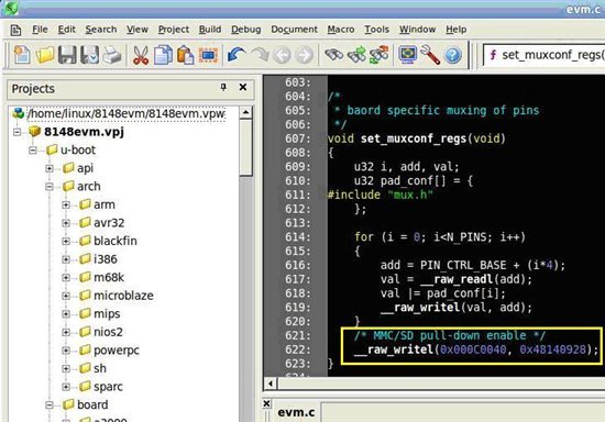
For example, in line 622 of the evm.c as shown below (TI814X SDK Ver. 05.00.00.26), we do not know what the 0x000C0040 means here.

Could anyone provide some document about this question?


  • Dexter,

    Tool generates C header files that are in the format that was used for OMAP3.

    That was a good solution assuming that the implementation of the

    PSP software would not change, but there is no way to control that.


    PSP software for DM814x used a different implementation,

    so the header files produced by the tool are not directly useable.

    Regards,

    Viet

  • Hi,

    Is there any interface to adjust the internal pull to high or low?

    We encounter a problem that the gpio is successfully set to the value we want, but if we touch the board, some gpio value will change, we guess the is due to the wrong setting of  internal pull registers.

    Thanks

    Rick

  • Please check the Data Manual doc for internal pull up/down for each pin.  Can you tell us which GPIO pin you are using?

    BR,

    Viet

  • Hi Viet,

    I can't find internal pull settings in 8148 TRM(sprugz8.pdf). The mentioned issue is found on gp2[10] and we are using the following pings as gpio:

    gp2[0], gp0[28], gp2[1], gp1[4], gp0[1], gp0[14], gp0[3], gp0[2], gp0[30], gp2[9], gp1[5], gp0[4], gp2[10]

    I guess we need a software configurable internal pull setting method rather than an external hw pull method mentioned in tms320dm8148.pdf

    Regards,

    Rick

  • Hello,

    My TI FAE was able to provide the bits definition for the PINCNTL registers for the DM814x.   Bit 18 must always be set.  

    I provided one example using gp0[18].

    #define PINCNTL_DEFAULT         0x00080000    // This bit must never change from default
    #define PINCNTL_PULL_DOWN       0x00040000    // Pulldown Selected
    #define PINCNTL_PULL_UP         0x00060000    // Pullup Selected
    #define PINCNTL_PULL_DISABLE    0x00050000    // Pullup/Pulldown Disabled
    #define PINCNTL_MUXMODE1        0x00000001    // Select Fcn 1
    #define PINCNTL_MUXMODE2        0x00000002    // Select Fcn 2
    #define PINCNTL_MUXMODE3        0x00000004    // Select Fcn 3
    #define PINCNTL_MUXMODE4        0x00000008    // Select Fcn 4
    #define PINCNTL_MUXMODE5        0x00000010    // Select Fcn 5
    #define PINCNTL_MUXMODE6        0x00000020    // Select Fcn 6
    #define PINCNTL_MUXMODE7        0x00000040    // Select Fcn 7
    #define PINCNTL_MUXMODE8        0x00000080    // Select Fcn 8

    #define pincntl_macro(x,y,z)    (*(U32 *)x = ( *(U32 *)x & PINCNTL_DEFAULT ) | y | z )

    #define pincntl_gp0_18()        pincntl_macro( 0x481408B8, PINCNTL_PULL_DISABLE, PINCNTL_MUXMODE8 ) // PINCNTL47  Debug Pin1


  • Hi,

    It is now defined in January Data Manual section Pin Multiplexing Control.

    BR,

    Viet

  • Viet

    Have there been any updates to the DM814x pin muxing tool in the last few months?.

    We are using v2.02.00.00, but we have not sucessfully set a GPIO pin yet (i.e an LED connected to it does not light) on our custom h/w.

    thanks

  • Steve:

    The current version is v2.2.1.0, but the only difference is a minor corection to the GUI.

    Program v2.2.0.0 can sometimes crash at startup.

    Do you have an output file from Pin Mux Tool (File ->Save -> design)>

    Regards,

    Michael T

  • Here is our pinmux.h file, zipped.

    We are trying to light an LED on GP0[1] in uboot, by pulling the pin low.

    thanks

    steve

    5672.pinmux-h.zip

  • I am assuming that you never see that LED lit up.  I would do this first since you are working with custom H/W.

    The address of the pinmux control register for GP0[1] is 0x4814081c.  The default value after power up for this register is 0x00060000 according to the DM814x EVM that I am using.  This means that the pin is weakly pulled up and disabled.  I would write a0x00040080 to that register which will change that pin to a pin down and in GP0[1] mode.  That should light up the led.  If that doesn't lit up the lit, then something wrong with your H/W.  So, next step is to ground the pin on the led that is driven by GP0[1].  If the led still doesn't lit up, chance are you got the led backwards.    I am assuming you have a 3.3V in series with a resister on the other side of the led.