This thread has been locked.

If you have a related question, please click the "Ask a related question" button in the top right corner. The newly created question will be automatically linked to this question.

TDA4VM: TP6594-Q1, Disable Watchdog function during run time after its configured

Part Number: TDA4VM

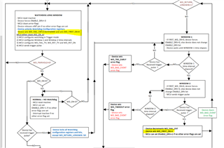
I am trying to disable the watchdog during runtime ( there are some use cases where we need to disable to watchdog before jumping to bootloader for flashing, during debugging etc..)


Looking at the manual, there is a need to use DISABLE_WDOG Pin. This pin is used in our design as an output, I believe this is not available for us to use.

Is there any other recommended sequence that can be followed to disable or turn off the watchdog. Like going to long window and then disabling the WD_EN pin??


  • Hi Shalhoob,

    Are you observing a watchdog reset from the PMIC? By default the software doesn't configure the PMIC watchdog.

    So on your custom board is it firing by default?

    If yes I will check with our board design experts to take a look at this.

    Best Regards,

    Keerthy

  • No We are trying to disable it after its started from software using software. What should be the steps to be followed to disable it.

  • No We are trying to disable it after its started from software using software

    Shalhoob,

    May I know which boot loader are you using to start the PMIC watchdog?
    By default we do NOT have any software to turn on PMIC watchdog on the SPL side.
    So I need more details on what software is being used to start the PMIC Watchdog?

    - Keerthy

  • Keerthy, Maybe i am not making it clear. We have watchdog implemented in our code. So its not anything default from TI code. We are starting the watchdog as part of our code. Now we have a usecase where we need to stop watchdog from resetting the SoC ( specifically for flashing usecase).

    How do we disable the watchdong after starting the watchdog and its actively monitoring.

  • Hello,

    When the watchdog is running a sequence you must first exit the sequence and return to the long window before disabling the watchdog.

    https://www.ti.com/lit/ds/symlink/tps6594-q1.pdf#page=84

    https://www.ti.com/lit/ds/symlink/tps6594-q1.pdf#page=358

    Once the PMIC has returned to the long window then the following bits can be configured: https://www.ti.com/lit/ds/symlink/tps6594-q1.pdf#page=83

    Regards,

    Chris

  • Thanks. How do we know if a sequence is ended/exited.

    What i tried was to send a pulse with twd_pulse after i send the i2c command to return to long window like below

    i2c( return to long window)

    GPIO High

    10ms

    GPIO Low

    i2c ( set wd_en to disable)

    But even in this case, 50% of the time the wdg is not getting disabled. the i2c read says its disabled but the board gets reset after the long window configured time.

  • Hello,

    How do we know if a sequence is ended/exited.

    The enable drive pin will go low.  The WD_FAIL_CNT and WD_FIRST_OK will be cleared.

    Is a PWM sourcing the watchdog?  If so, then leave the PWM running until after confirming that the WD_FIRST_OK=0.  Once confirmed then disable the WDOG and then turn off the PWM.  

    Regards,

    Chris

  • The enable drive pin will go low.  The WD_FAIL_CNT and WD_FIRST_OK will be cleared.

    In our design EN_DRV pin is not connected to the SOC (TDA4VM). Is there any other way to force exit a sequence or read some other registers to know if the sequence exited and the device is in long window?

  • Hello,

    I am not aware of a means for force exit.  When WD_FIRST_OK=1 then the sequence is running.  When WD_FIRST_OK=0 then the WDOG is in the long window. I2C Address 0x12, register 0x0A, bit 5 (https://www.ti.com/lit/ds/symlink/tps6594-q1.pdf#page=362 ).

    www.ti.com/.../tps6594-q1.pdf

    Can you send two pulses to ensure that if your in either window 1 or window 2 that the PMIC goes to the long window?

    i2c( return to long window)

    GPIO High

    10ms

    GPIO Low

    10ms

    GPIO High

    10ms

    GPIO Low

    i2c ( set wd_en to disable)

    Regards,

    Chris

  • Thanks. I tried polling the WD_First_OK and when its 0, i wrote the wd_en to disable. After this i had a while loop counting the number of seconds. the watchdog reset the SOC after 8 seconds ( this is the long window time i have configured)

    i2c( return to long window)

    GPIO High

    10ms

    GPIO Low

    10ms

    GPIO High

    10ms

    GPIO Low

    i2c ( check if wd_first_ok is cleared)

    i2c ( set wd_en to disable)

    while ( wait for x seconds)

  • Hello,

    The behavior described is not matching the expected.  Can you confirm that you are using the latest PMIC silicon?  The PMIC configurations should match what is described in the document:

    www.ti.com/.../slvuby7a.pdf

    Device I2C Address Register Address 0x01 Register Address 0x02 Register Address 0x03
    TPS6594141B 0x48 0x82 0x1B 0x01
    LP876441B 0x4C 0x86 0xB1 0x01

    Given the long window expiration matches what you have programmed, the PMIC is entering the Long window correctly but the WD_EN is not being cleared.

    1. Can you confirm what is actually being sent on the I2C bus?
      1. The PMIC is configured to use a dedicated I2C bus on GPIO1 and GPIO2.  Because you are using the trigger watchdog instead of the Q&A watchdog us GPIO2 configured as TRIG_WDOG?
      2. Please confirm the order of operation between configuring the watchdog and changing the GPIO2/GPIO1 interface.
    2. Can you confirm that you are writing to address 0x12, register address 0x09 and bit6 to clear WD_EN?
    3. Please confirm status of the I2C CRC, an incorrect CRC will cause an I2C write to be ignored.

    Regards,

    Chris

  • Given the long window expiration matches what you have programmed, the PMIC is entering the Long window correctly but the WD_EN is not being cleared.

    That is my understanding as well

    The PMIC is configured to use a dedicated I2C bus on GPIO1 and GPIO2.  Because you are using the trigger watchdog instead of the Q&A watchdog us GPIO2 configured as TRIG_WDOG?

    The WKUP i2c is used to configure the PMIC including teh watchdog registers. For watchdog the slave address of 0x12 is used

    Please confirm the order of operation between configuring the watchdog and changing the GPIO2/GPIO1 interface.

    1) Pinmux is configured as GPIO. GPIO2 pin is pulled low

    2) Configure GPIO2_CONF Register to 0x2A to to slave address 0x48

    3) Enable  Watchdog

    4) Return to Longwindow bit set

    5) configurewindow1,  window2 timings , long window timing, wdt mode, and other thresholds

    then when the application is ready, return to longwindow is cleared and GPIO pin is pulled high for 10ms

    Can you confirm that you are writing to address 0x12, register address 0x09 and bit6 to clear WD_EN?

    That is correct when i read back it gives the following b10101001, 6th bit is set to 0

    Please confirm status of the I2C CRC, an incorrect CRC will cause an I2C write to be ignored.

    Yes CRC is not enabled. I am able to read other registers and can confirm it changes as expected ( ex. wd_first_oK)

    The behavior described is not matching the expected.  Can you confirm that you are using the latest PMIC silicon?  The PMIC configurations should match what is described in the document:

    This is what I am seeing

    Slave address 0x48

    DEV_REV = 0x82  

    NVM_CODE_1 = 0x13

    NVM_CODE_2 = 0x4

  • Hello,

    Thank you for the NVM information.  I was referencing the incorrect PDN.  The correct PDN is found here.

    I have recreated the test but I added a step where after configuring GPIO2_CONF to 0x2A I noticed that the WD_PWRHOLD was getting set.  Prior to enabling the test I cleared the WD_PWRHOLD bit.  

    I do not set the return to longwindow bit until after the sequence starts.

    /cfs-file/__key/communityserver-discussions-components-files/791/test_5F00_trigWdog.xlsx

    (1) Set NSLEEP Bits to 0x03

    (2) Clear interrupts (ENABLE_INT, BIST_PASS)

    (3) GPIO2_CONF = 0x2A

    (4) Disable watchdog, clear WD_PWRHLD

    (5) Configure win1, win2, etc

    (6) Enable watchdog

    (7) Start PWM

    (8) Confirm WD_FIRST_OK=1 (in sequence)

    (8) Set WD_RETURN_LONGWIN

    (9) Confirm WD_FIRST_OK=0 (in long window)

    (10) Stop PWM

    (11) Disable watchdog

    Can you recreate this on your setup?

    Regards,

    Chris

  • Thanks. Now i am able to get this working, The issue was doing the GPIO sequence to force exit a sequence is causing the issue. Now i am having to wait until the window-2 time expires. Do you know why this could be the reason?

    GPIO High

    10ms

    GPIO Low

    Also per the below table, the wdg should be enabled by default. But that is not the case. how do i find the correct NVM settings for the PMIC i am using.

  • Hello,

    The issue was doing the GPIO sequence to force exit a sequence is causing the issue.

    Can you describe this in more detail?  I am not understanding how a GPIO sequence would force exit a sequence?  In order to leave the wd long window mode and enter the trigger watchdog mode a trigger pulse is required, is this what you are referring to?

    https://www.ti.com/lit/ds/symlink/tps6594-q1.pdf#page=87

    Also per the below table, the wdg should be enabled by default. But that is not the case. how do i find the correct NVM settings for the PMIC i am using.

    I am not certain.  The values you provided should mean that the NVM is a match and the watchdog is enabled by default.  I would need to do some additional investigation.  As previously asked, if the I2C crc has not been enabled, then you should be able to read out the register CRC information.  Slave address 0x48 register addressed 0xF0 through 0xF3.  If you can provide, then I can compare with the database.

    Regards,

    Chris

  • Slave address 0x48 register addressed 0xF0 through 0xF3

    F0 - 0x64

    F1 - 0xA3

    F2 - 0x23

    F3 - 0xFC

  • Can you describe this in more detail?  I am not understanding how a GPIO sequence would force exit a sequence? 

    So to make sure we are in long window ( or reach Long window ) as per the datasheet it needs a sequence to complete. And one of the way mentioned was to a Pulse trigger. So what we did was send i2c for return long window and then triggered GPIO pulse 2 times ( to make sure atleast one is in window1) following the below quote. If we are doing this then it does not work.

    Can you send two pulses to ensure that if your in either window 1 or window 2 that the PMIC goes to the long window?

    i2c( return to long window)

    GPIO High

    10ms

    GPIO Low

    10ms

    GPIO High

    10ms

    GPIO Low

    i2c ( set wd_en to disable)

    Regards,

    Chris

  • Hello,

    Thank you for the explanation and also providing the CRC registers.  The CRC values match what is expected.  I do not have any resolution regarding this comment.  

    Also per the below table, the wdg should be enabled by default. But that is not the case. how do i find the correct NVM settings for the PMIC i am using.

    The DISABLE_WDOG feature on GPOI8 may explain why the watchdog is disabled, but the actual value of WD_EN should be '1'.

    Regards,

    Chris