This thread has been locked.

If you have a related question, please click the "Ask a related question" button in the top right corner. The newly created question will be automatically linked to this question.

How do I access the physical pins of the GPIO on the TDA4AL/TDA4VM?

Other Parts Discussed in Thread: TDA4VM, SK-TDA4VM, SYSCONFIG

Hello,

my question is how do I actually access the pins of the GPIO on the board on the TDA4AL/TDA4VM?
I have documentation on how to program a GPIO driver but it needs to be tested and I can't find any information about that.

Thanks in advance and kind regards,
Johannes

  • Hi Johannes,

    Could you share which SDK is being used, which core that needs the GPIO access, and which board is being used (EVM board, SK board, or custom board)?

    For the EdgeAI SDK on the SK-TDA4VM board where GPIO is accessed via a driver running on the A72 core, we have the following documentation, where sample code can be accessed from the Github repositories linked inside the documentation: https://software-dl.ti.com/jacinto7/esd/processor-sdk-linux-edgeai/TDA4VM/08_06_00/exports/docs/devices/TDA4VM/linux/pi_hdr_programming.html

    Otherwise, for PSDK RTOS on the EVM board, we have the following documentation that has some sample code: https://software-dl.ti.com/jacinto7/esd/processor-sdk-rtos-jacinto7/08_06_00_12/exports/docs/pdk_jacinto_08_06_00_31/docs/userguide/jacinto/modules/gpio.html

    Regards,

    Takuma

  • Hi Takuma,

    I meant that I wanted to access to pins physically as I want to test my GPIO with a LED to turn it on and off for example.

    The board that I have available is a TDA4VM with a J721e EVM. Later I need to use the driver for the TDA4AL with the J721S2 as well. So I would be information about how to access the GPIO pins physically on both boards.

    Is it necessary to have some sort of expander module for the pins, since there don't seem to be any traditional GPIO pins on the board?

    Kind regards,
    Johannes

  • Hey there,

    I just got a hint from a coworker. He mentioned there might be some sort of loopback pin. Is there one? If so then I could circumvent the issue of accessing somewhere on the board.

    Kind regards,
    Johannes

  • Hi Johannes,

    I would need to get back on the loopback pin question. But as for GPIO on the EVM, there are pins that are configured as default for ADC or CAN that may be able to be pinmuxed to be GPIO. 

    Due to bandwidth issues on our side, it will take a little over a week for us to get a deeper dive into enabling the pins on the EVM as GPIO - expect the week of the 24th.

    However, if you would like to take a look at it in the meantime, I will describe what the task would look like:

    1. Identify an exposed pin on the board. For example, J29 near the CAN connectors.
    2. Reference the schematic file of the Common Processor Board Design files (from https://www.ti.com/tool/J721EXSOMXEVM PROC079E3C(001)_SCH.pdf) to find which pin on the SoC the header is connected to. For example, pin 1 of J29 is connected to MCU_MCAN0_TX
    3. Reference the datasheet of TDA4VM to see if the pin (MCU_MCAN0_TX for example) can be pinmuxed as GPIO: https://www.ti.com/document-viewer/tda4vm/datasheet
    4. And then pinmux the pin as GPIO, either as a device tree overlay for Linux, or through API calls for RTOS. The method for pinmuxing differs between Linux and RTOS:

      Linux: https://e2e.ti.com/support/processors-group/processors/f/processors-forum/918654/faq-tda4vm-dra829-am65xx-linux-configuring-gpios

      RTOS: https://e2e.ti.com/support/processors-group/processors/f/processors-forum/1126741/faq-tda4vm-using-pdk-gpio-driver

    Regards,

    Takuma

  • Hi Takuma,

    thanks for the detailed answer and your work that you put into figuring out how this works.

    While you are busy getting the details, I would already try to figure out as much as possible on my side as well.

    Kind regards,
    Johannes

  • Hi Johannes,

    Thank you for your patience.

    Regards,

    Takuma

  • Hi Johannes,

    I can start taking a deeper look on April 27, but were you able to make progress on your side?

    Regards,

    Takuma

  • Hi Takuma,

    I was able to make some progress. But it's not really resolved yet.

    So far we identified a button called SW2_SOM on the J721S2 EVM (we are on the TDA4AL already) which according to our current understanding can work as input for the GPIO as GPIO0_11. 
    My colleagues also saw some LEDs that could be potentially used for checking if the output works. Sadly I couldn't verify their connection to the GPIO.

    And now I am on the software side. I figured out what I potentially need in order to get my own GPIO driver working. Sadly the documentation that I have for the TDA4AL is incomplete. So I need to hope that nothing changed from the TDA4VM in regard to the GPIO driver.

    According to my understanding I need device INTCs enabled for interrupt support, clocking needs to be enabled, module reset needs to be enabled, and some form of multiplexing via the CTRLMMR_PADCONFIG registers. This leads to a couple of questions for me.
    -What are device INTCs?
    -Is the clocking enabled by a bootloader (in our case this is uboot)?
    -How is the module reset enabled for the GPIO?
    -And assumingly the most important question how does the pinmuxing work? How do the CTRLMMR_PADCONFIG register correspond to the GPIO pins/banks?

    Sorry for the now quite big amount of questions.

    Kind regards,
    Johannes

  • Hi Johannes,

    Can you clarify whether we are going down the device tree route using Linux, or the RTOS route with using PDK to configure pinmuxing? I will assume Linux in the following question/answer.

    To answer some of your questions:

    -What are device INTCs?

    INTC stands for Interrupt Controllers and this is specifically PRU-ICSSG local interrupt controller. Details of it can be found in Section 6.6.7, PRU_ICSSG Local INTC section of the technical reference manual: https://www.ti.com/lit/zip/spruil1 (note that this documentation is for TDA4VM, but should be similar to TDA4AL). Chapter 9 of the same TRM is a dedicated chapter for interrupts. Looking through device tree for TDA4VM, it seems GIC (General Interrupt Controller) is set for main_gpio_intr: https://git.ti.com/cgit/ti-linux-kernel/ti-linux-kernel/tree/arch/arm64/boot/dts/ti/k3-j721e-main.dtsi?h=ti-linux-5.10.y#n163 and this is configured to be used by each GPIO: https://git.ti.com/cgit/ti-linux-kernel/ti-linux-kernel/tree/arch/arm64/boot/dts/ti/k3-j721e-main.dtsi?h=ti-linux-5.10.y#n1254

    -And assumingly the most important question how does the pinmuxing work? How do the CTRLMMR_PADCONFIG register correspond to the GPIO pins/banks?

    Easiest tool to use to see which muxmode corresponds to GPIO would be to use the sysconfig tool: https://dev.ti.com/sysconfig/#/start. I checked, and J721S2 is available for the tool. For more details on what the pins can be pinmuxed to, searching "gpio0_11" in the datasheet for TDA4AL (J721S2) will give you more information: https://www.ti.com/lit/ds/symlink/tda4al-q1.pdf?ts=1682641210835&ref_url=https%253A%252F%252Fwww.ti.com%252Fproduct%252FTDA4AL-Q1%253FkeyMatch%253DJ721S2

    -Is the clocking enabled by a bootloader (in our case this is uboot)?
    -How is the module reset enabled for the GPIO?

    Not quite sure on these, but what I can say is that in both u-boot and Linux kernel's device tree, I see the clocks are defined for GPIO.

    Regards,

    Takuma

  • Hi Johannes,

    Giving you a small update as I had a bit of difficulty on my end for pinmuxing GPIO. There are two user LEDs on the common processor board that can be controlled from user space, and I am able to toggle this with the following sequence:

    cd /sys/class/gpio/
    
    echo 486 > /sys/class/gpio/export
    
    cd gpio486
    
    echo out > direction
    
    echo 1 > value
    
    echo 0 > value

    As a warning, user LEDs are rather hidden. Attached is a picture of one user LED on:

    Currently trying to see if I can make a device tree overlay for individual ADC pins and pinmux one for GPIO. Making it an interrupt will be the step after that.

    Following is mainly FYI: The value 486 can be determined by running gpioinfo gpiochip2 and searching for USER_LED1 (which corresponds to line 22). Running gpiodetect shows gpiochip2 corresponds to [3-0022] which is I2C bus 3, address 22 since these GPIOs are connected to a I2C GPIO expander device. Running cat /sys/class/gpio/gpiochip464/label will show that gpiochip464 corresponds to 3-0022, meaning the base value for USER_LED1's GPIO value is 464. 464+22=486.

    Regards,

    Takuma

  • Hi Takuma,

    thanks already for the work you are putting into this.

    Can you clarify whether we are going down the device tree route using Linux, or the RTOS route with using PDK to configure pinmuxing? I will assume Linux in the following question/answer.

    This might be unusual but I need to write the GPIO driver for the TDA4AL for our company's OS. I am not sure how this will affect the way how all the steps are done.

    Giving you a small update as I had a bit of difficulty on my end for pinmuxing GPIO. There are two user LEDs on the common processor board that can be controlled from user space, and I am able to toggle this with the following sequence:

    I am a bit relieved that I am not the only one who has difficulties with this thing here. 
    But regarding the LEDs. Are you talking about LD8 and LD9?

    Kind regards,
    Johannes

  • Hi Johannes,

    This might be unusual but I need to write the GPIO driver for the TDA4AL for our company's OS.

    Sure, the suggestions from TI will, naturally, be based on TI's Linux or RTOS examples. But general flow should be similar to our examples, where pinmuxing needs to happen, initialization of GPIO pin's direction, interrupts, etc, and then usage.

    But regarding the LEDs. Are you talking about LD8 and LD9?

    Yes, these are already pinmuxed/defined in device tree for 8.6 release of TDA4AL's SDK. These would be a good example for enabling and testing GPIO since the LEDs are onboard the EVM. However, as a warning, these are connected to an I2C device that expands the number of GPIO pins, so it's not a direct connection from SoC to LED (meaning the device tree is a little different). However, from a Linux userspace point of view, I did not see any difference from a direct connection to LED pins when toggling the pin through sysfs.

    Regards,

    Takuma

  • Hi Takuma,

    Giving you a small update as I had a bit of difficulty on my end for pinmuxing GPIO. There are two user LEDs on the common processor board that can be controlled from user space, and I am able to toggle this with the following sequence:

    Fullscreen
    1
    2
    3
    4
    5
    6
    7
    8
    9
    10
    11
    cd /sys/class/gpio/
    echo 486 > /sys/class/gpio/export
    cd gpio486
    echo out > direction
    echo 1 > value
    echo 0 > value
    XXXXXXXXXXXXXXXXXXXXXXXXXXXXXXXXXXXXXXXXXXXXXXXXXX

    I could finally follow your example for Linux. It worked great which is good news for me.

    Now the next step is to replicate it with my own driver.

    Following is mainly FYI: The value 486 can be determined by running gpioinfo gpiochip2 and searching for USER_LED1 (which corresponds to line 22). Running gpiodetect shows gpiochip2 corresponds to [3-0022] which is I2C bus 3, address 22 since these GPIOs are connected to a I2C GPIO expander device. Running cat /sys/class/gpio/gpiochip464/label will show that gpiochip464 corresponds to 3-0022, meaning the base value for USER_LED1's GPIO value is 464. 464+22=486.

    Does this mean that USER_LED1 can only be accessed via an I2C GPIO expander? If so, is there an LED that can be accessed without I2C in order to keep the code as simple as possible?

    But as a conclusion, the procedure as a whole is?

    • Pinmux a pin
      • Write into its PADCONFIG register in order to do the pinmuxing
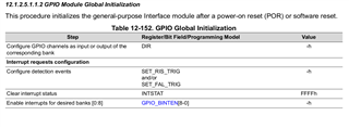
    • Do the global initialization of the GPIO 
      • With the routine described in the TRM, as seen in the picture
    • Reading from/Writing to the GPIO registers dedicated to the different banks starting from the addresses 0060 0000h for GPIO and 4210 0000h for WKUP_GPIO

    Is there something else that is missing?

  • Hi Johannes,

    Does this mean that USER_LED1 can only be accessed via an I2C GPIO expander? If so, is there an LED that can be accessed without I2C in order to keep the code as simple as possible?

    Yes, USER_LED1 can only be accessed via the I2C GPIO expander, since this is a hardware design of the board where the LED is physically connected to a I2C GPIO expander device. And no, looking through schematics it seems all the user LEDs are connected via this I2C GPIO expander. Other LEDs on the EVM are mainly status LEDs not controllable by software. Currently looking for a good GPIO pin that is unused, pinmuxable as GPIO, and directly connected between a physical header and SoC pin, so that we could connect an external LED to use as a user LED.

    But as a conclusion, the procedure as a whole is?

    If writing a driver from scratch, the RTOS driver might be easier to follow. I would recommend reading through this FAQ: https://e2e.ti.com/support/processors-group/processors/f/processors-forum/1126741/faq-tda4vm-using-pdk-gpio-driver

    Essentially 4 steps:

    1. Pinmux
    2. Set base address
    3. Initialize GPIO pins (like direction and interrupts)
    4. Write to the pin

    The flow described in your post is a good understanding.

    Regards,

    Takuma