Hi TI
A customer is inquiring about the difference between Datasheet and EVM Schematic for VSS_RTC processing.
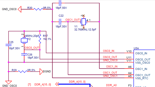
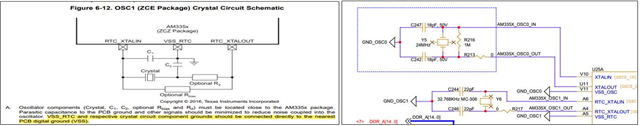
Can I understand that VSS on Datasheet and GND_OSC1 on EVM circuit diagram are the same? Or ask if EVM designed it without following the guide. I think GND_OSC1 is the nearest PCB digital ground VSS...
TI, please explain. ^^
Thanks
Regards,
Jack