This thread has been locked.

If you have a related question, please click the "Ask a related question" button in the top right corner. The newly created question will be automatically linked to this question.

TDA4VM: Measure power consumption (contd.)

Part Number: TDA4VM
Other Parts Discussed in Thread: INA226

Hello!

It seems the way to measure the power consumption using the INA226:es as described here is no longer valid.

The newer versions of the k3-j721e-common-proc-board.dts is defining the exp2 - gpio expander, and hogs the
line that switches between the two sets of INA226 chips.

How can I measure all of the 32 values in this setup? The drivers for the gpio expanders are loaded, so
I have tried the following:

root@j7-evm:~# gpiodetect
gpiochip0 [3-0020] (16 lines)
gpiochip1 [3-0022] (24 lines)
gpiochip2 [6-0020] (8 lines)
gpiochip3 [9-0020] (8 lines)
gpiochip4 [42110000.gpio] (84 lines)
gpiochip5 [600000.gpio] (128 lines)
gpiochip6 [601000.gpio] (36 lines)
gpiochip7 [4-0020] (8 lines)

The chip that controls the i2c-switch for the INA226:es is gpiochip1 (on main_i2c0, which is i2c bus 3).

The expander looks like this:

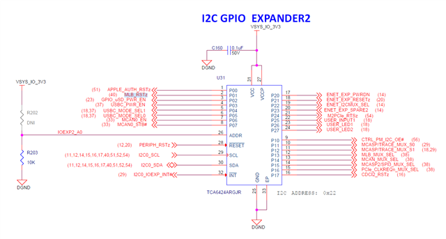
The lines have these names/numbers:

root@j7-evm:~# gpioinfo
...
gpiochip1 - 24 lines:
        line   0:      unnamed       unused   input  active-high
        line   1:      unnamed       unused   input  active-high
        line   2:      unnamed "fixedregulator-sd" output active-high [used]
        line   3:      unnamed       unused   input  active-high
        line   4:      unnamed       unused   input  active-high
        line   5:      unnamed       unused   input  active-high
        line   6:      unnamed       unused   input  active-high
        line   7:      unnamed       unused   input  active-high
        line   8:      unnamed "CTRL_PM_I2C_OE" output active-high [used]
        line   9:      unnamed "MCASP/TRACE_MUX_S0" output active-high [used]
        line  10:      unnamed "MCASP/TRACE_MUX_S1" output active-low [used]
        line  11:      unnamed       unused   input  active-high
        line  12:      unnamed       unused   input  active-high
        line  13:      unnamed       unused   input  active-high
        line  14:      unnamed       unused   input  active-high
        line  15:      unnamed       unused   input  active-high
        line  16:      unnamed       unused   input  active-high
        line  17:      unnamed       unused   input  active-high
        line  18:      unnamed       unused   input  active-high
        line  19:      unnamed       unused   input  active-high
        line  20:      unnamed      "reset"  output  active-high [used]
        line  21:      unnamed       unused   input  active-high
        line  22:      unnamed       unused   input  active-high
        line  23:      unnamed       unused   input  active-high

So I tried to see what value line 8 had:

root@j7-evm:~# gpioget gpiochip1 8
gpioget: error reading GPIO values: Device or resource busy

How can I change the output of that port so that I can read the other 16 INA226 measurements?

Thanks,

/Bo

  • Hi,

    Which SDK version are you using?

  • newer versions of the k3-j721e-common-proc-board.dts is defining the exp2 - gpio expander, and hogs the
    line that switches between the two sets of INA226 chips.

    The gpio expander is an enabler for pm_i2c. Go through the FAQ fully. SOC GPIO needs to be toggled to switch to measuring the second set of 16 INAs. The GPIO number in Linux might have changed but that's the way to switch.

    Regards,

    Keerthy 

  • Hi,

    Which SDK version are you using?

    I'm using version 8.05.00.08

    Thanks! /Bo

  • The gpio expander is an enabler for pm_i2c. Go through the FAQ fully. SOC GPIO needs to be toggled to switch to measuring the second set of 16 INAs. The GPIO number in Linux might have changed but that's the way to switch.

    Did you read my question in full? I understand how it is "supposed" to work, but the GPIO pin can't be switched. "Device or resource busy".

    The link that I linked to above uses the old sysfs-way to interact with gpio. This is deprecated and should not be used, therfore an updated FAQ on how to read all the 32 measurements should be developed.

    In the dts:

    	exp2: gpio@22 {
    		compatible = "ti,tca6424";
    		reg = <0x22>;
    		gpio-controller;
    		#gpio-cells = <2>;
    
    		p08-hog {
    			/* P10 - PM_I2C_CTRL_OE */
    			gpio-hog;
    			gpios = <8 GPIO_ACTIVE_HIGH>;
    			output-high;
    			line-name = "CTRL_PM_I2C_OE";
    		};
    

    You see that the pin is hogged. How can it be released so that I can take ownership in user space?

    BR

    /Bo

  • You see that the pin is hogged. How can it be released so that I can take ownership in user space?

    Bo,

    I am bot sure if you understand that you need 2 things to accomplish what you are asking.

    The I2C expander has to be hogged to enable the first level of PM_i2C access.

    The second is what you are asking which is a SOC GPIO and that is not hogged.

    The SOC GPIO1_0 is used to control the Switching between first set of 16 INAs Vs 2nd set.
    So you need to toggle GPIO1_0 to High to read the second set of 16 INAs.

    If you see the FAQ: e2e.ti.com/.../faq-tda4vm-measuring-power-consumption-of-the-device

    echo 1 > /sys/class/gpio/gpio216/value

    This is what is describing. On the latest SDK the 216 might be something else that we can find out by:

    ls /sys/class/gpio/gpiochip*/label & look for the gpiochip* that points to 601000.gpio.

    Let me know if you still are not clear.

    - Keerthy


  • I am bot sure if you understand that you need 2 things to accomplish what you are asking.

    The I2C expander has to be hogged to enable the first level of PM_i2C access.

    The second is what you are asking which is a SOC GPIO and that is not hogged.

    You are abolutely correct. I have misstaken the "enable" signal for the "bank-selection" signal.

    This is the output of my ls:

    root@j7-evm:~# ls /sys/class/gpio/gpiochip*/label -al
    -r--r--r-- 1 root root 4096 Apr 18 12:25 /sys/class/gpio/gpiochip200/label
    -r--r--r-- 1 root root 4096 Apr 18 12:25 /sys/class/gpio/gpiochip208/label
    -r--r--r-- 1 root root 4096 Apr 18 12:25 /sys/class/gpio/gpiochip244/label
    -r--r--r-- 1 root root 4096 Apr 18 12:25 /sys/class/gpio/gpiochip372/label
    -r--r--r-- 1 root root 4096 Apr 18 12:25 /sys/class/gpio/gpiochip456/label
    -r--r--r-- 1 root root 4096 Apr 18 12:25 /sys/class/gpio/gpiochip464/label
    -r--r--r-- 1 root root 4096 Apr 18 12:25 /sys/class/gpio/gpiochip472/label
    -r--r--r-- 1 root root 4096 Apr 18 12:25 /sys/class/gpio/gpiochip496/label
    root@j7-evm:~# cat /sys/class/gpio/gpiochip*/label
    4-0020
    601000.gpio
    600000.gpio
    42110000.gpio
    9-0020
    6-0020
    3-0022
    3-0020
    

    So, it seems to be gpiochip208 that corresponds to 601000.gpio. So I changed in the script to 208 (GPIO1_0) and tried to:

    root@j7-evm:~# echo 208 > /sys/class/gpio/export
    root@j7-evm:~# echo out > /sys/class/gpio/gpio208/direction
    root@j7-evm:~# echo 0 > /sys/class/gpio/gpio208/value
    root@j7-evm:~# ./power_snapshot.sh
    Rail-Name                               Voltage(mV)             Current(mA)             Power(uW)
    
    VDD_MCU_0V85                            858                     605                     525000
    VDD_MCU_RAM                             864                     8                       12500
    VDA_MCU_1V8                             1801                    19                      31250
    VDD_MCUIO_3V3                           3298                    8                       25000
    VDD_MCUIO_1V8                           1801                    3                       0
    VDD_CORE_0V8                            804                     3930                    3162500
    VDD_CORE_RAM                            849                     35                      31250
    VDD_CPU_RAM                             848                     100                     81250
    VDD_CPU_AVS                             855                     2281                    1950000
    VDDR_BIAS_1V1                           1103                    53                      62500
    VDDR_IO_DV                              1100                    74                      81250
    VDD_PHYCORE_0V8                         794                     209                     162500
    VDA_PLL_1V8                             1801                    47                      81250
    VDD_PHYIO_1V8                           1801                    152                     275000
    VDA_USB_3V3                             3290                    5                       18750
    SPARE_RAIL_0                            0                       0                       0
    root@j7-evm:~# echo 1 > /sys/class/gpio/gpio208/value
    root@j7-evm:~# ./power_snapshot.sh
    Rail-Name                               Voltage(mV)             Current(mA)             Power(uW)
    
    VDD_MCU_0V85                            858                     605                     525000
    VDD_MCU_RAM                             864                     8                       12500
    VDA_MCU_1V8                             1801                    19                      31250
    VDD_MCUIO_3V3                           3296                    8                       25000
    VDD_MCUIO_1V8                           1801                    3                       0
    VDD_CORE_0V8                            804                     3930                    3162500
    VDD_CORE_RAM                            849                     35                      31250
    VDD_CPU_RAM                             848                     101                     81250
    VDD_CPU_AVS                             855                     2282                    1950000
    VDDR_BIAS_1V1                           1100                    53                      62500
    VDDR_IO_DV                              1099                    74                      81250
    VDD_PHYCORE_0V8                         794                     208                     162500
    VDA_PLL_1V8                             1801                    47                      81250
    VDD_PHYIO_1V8                           1801                    152                     275000
    VDA_USB_3V3                             3290                    5                       18750
    SPARE_RAIL_0                            0                       0                       0
    

    But as you can see, the second call to the script still returns the first 16 values.

    Thanks for helping out.

    /Bo

  • Hi,

    Please switch to 1 & double check if the value is indeed set to 1 by reading:

    cat /sys/class/gpio/gpio208/value

    That should enable measuring other 16.

    - Keerthy

  • Please switch to 1 & double check if the value is indeed set to 1 by reading:

    cat /sys/class/gpio/gpio208/value

    It doesn't change its value.

    root@j7-evm:~# echo 1 > /sys/class/gpio/gpio208/value
    root@j7-evm:~# cat /sys/class/gpio/gpio208/value
    0
    root@j7-evm:~#
    

    /B

  • The pinmux for GPIO0_1 set the register 0x11C204 to 0x40007

    'devmem2 0x11C204 w 0x40007'

    Can you try this devmem2 command before toggling the GPIO1_0?

    - Keerthy

  • 'devmem2 0x11C204 w 0x40007'

    Can you try this devmem2 command before toggling the GPIO1_0?

    Yes, success!

    root@j7-evm:~# devmem2 0x11C204 w 0x40007
    /dev/mem opened.
    Memory mapped at address 0xffffaaa3e000.
    Read at address  0x0011C204 (0xffffaaa3e204): 0x08214007
    Write at address 0x0011C204 (0xffffaaa3e204): 0x00040007, readback 0x00040007
    root@j7-evm:~# echo 1 > /sys/class/gpio/gpio208/value
    root@j7-evm:~# cat /sys/class/gpio/gpio208/value
    1
    root@j7-evm:~# ./power_snapshot.sh
    Rail-Name                               Voltage(mV)             Current(mA)    )
    
    VDD_IO_1V8                              1798                    12             0
    VDD_IO_3V3                              3304                    36             0
    VDD_SD_DV                               1801                    7              0
    VDD1_RAIL                               1803                    5              0
    VDD2_RAIL                               1101                    110            0
    VDDQ_LPDDR4_DV                          1100                    14             0
    VSYS_MCUIO_1V8                          1801                    3              0
    VSYS_MCUIO_3V3                          3296                    29             0
    VSYS_IO_1V8                             1794                    356            0
    VSYS_IO_3V3                             3303                    78             0
    VCC_12V0                                12051                   24             0
    VSYS_5V0                                5008                    90             0
    VSYS_3V3                                3313                    98             0
    VSYS_3V3_SOM                            3311                    293            0
    VDDA_DLL_0V8                            801                     17             0
    EXP_3V3_RAIL                            3298                    774            0

    The gpio port answers "1" and the second 16 readings are now available.

    How does this differ from my own pinmux in the dts?

    I have added:

    &main_pmx0 {
    	ina226_selection_pins_default: ina226-selection-pins-default {
    		pinctrl-single,pins = <
    			J721E_IOPAD(0x204, PIN_INPUT, 7) /* (AD5) UART1_RTSn.GPIO1_0 */
    		>;
    	};
    

    What have I done wrong in my pinmux?

    Thanks for the patience, and all the help!

    /Bo

  • Hi,

    That is just a definition. ina226-selection-pins-default is not being hooked to any platform device tree node that gets probed.

    See for example:

    We define & then use the sw10_button_pins default inside the gpio_keys node.
    So ina226-selection-pins-default should ideally be hooked as pinctrl-0 for ina226 node.
    Otherwise this will not take effect.

    - Keerthy

  • Thanks for your answer Keerthy,

    If I add a hook for the ina226 selection pin, it becomes unavailable from user space.

    Since it is an output, I added it as a gpio-led below the gpio-keys, like this:

    	gpio_keys: gpio-keys {
    		compatible = "gpio-keys";
    		autorepeat;
    		pinctrl-names = "default";
    		pinctrl-0 = <&sw10_button_pins_default &sw11_button_pins_default>;
    
    		sw10: sw10 {
    			label = "GPIO Key USER1";
    			linux,code = <BTN_0>;
    			gpios = <&main_gpio0 0 GPIO_ACTIVE_LOW>;
    		};
    
    		sw11: sw11 {
    			label = "GPIO Key USER2";
    			linux,code = <BTN_1>;
    			gpios = <&wkup_gpio0 7 GPIO_ACTIVE_LOW>;
    		};
    	};
    
    	ina_selection: ina-selection {
    		compatible = "gpio-leds";
    		pinctrl-names = "default";
    		pinctrl-0 = <&ina226_selection_pins_default>;
    
    		ina226: ina226 {
    			label = "GPIO INA Sel";
    			gpios = <&main_gpio1 0 GPIO_ACTIVE_HIGH>;
    		};
    	};


    But when I try to control it by exporting gpio 208:

    root@j7-evm:~# echo 208 > /sys/class/gpio/export
    -sh: echo: write error: Device or resource busy

    as well as the gpioset:

    root@j7-evm:~# gpioset gpiochip6 0=1
    gpioset: error setting the GPIO line values: Device or resource busy

  • You should keep the GPIO control from Linux user space so you should not be adding that in DTS if you want to control from user space else like you observed you will see that it will be reserved.

    As a quick hack you can try below:

    &main_pmx0 {
    sw10_button_pins_default: sw10-button-pins-default {
    pinctrl-single,pins = <
    J721E_IOPAD(0x0, PIN_INPUT, 7) /* (AC18) EXTINTn.GPIO0_0 */
    J721E_IOPAD(0x204, PIN_INPUT, 7) /* (AD5) UART1_RTSn.GPIO1_0 */
    >;
    };
    };

    That should be taking care of pinmux & then you should be able to toggle GPIO from Linux user space.

    - Keerthy

  • Thank you Keerthy, that worked perfectly.

    All I had to do to make my own code work is to remove the hook:

    	ina_selection: ina-selection {
    		compatible = "gpio-leds";
    		pinctrl-names = "default";
    		pinctrl-0 = <&ina226_selection_pins_default>;
    
    //		ina226: ina226 {
    //			label = "GPIO INA Sel";
    //			gpios = <&main_gpio1 0 GPIO_ACTIVE_HIGH>;
    //		};
    	};

    /Bo