This thread has been locked.

If you have a related question, please click the "Ask a related question" button in the top right corner. The newly created question will be automatically linked to this question.

AM625: McASP configuration - GPIO Mux

Part Number: AM625
Other Parts Discussed in Thread: SYSCONFIG, TLV320AIC3106

Hi AM62x support,

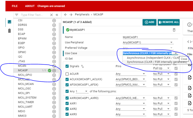
Our customer is trying to configure the GPIO multiplexer on the AM62 to enable the McASP.  They've tried two methods:

- Using CCS to configure U-Boot.  Led to an error importing the .sysconfig file from the SDK.

- Use Sysconfig, but they get an empty configuration file, so they couldn't setup the rest of the board for the project. 

They're working on the EVM.

Can you send the right starting point here?  What document should they be following for this process.

Thanks,
Darren

  • Darren

    I you asking about the pinmux (padconfig) configuration using SysConfig or configuring the SDK?

    If pinmux, can you elaborate on GPIO Multiplexer?  The SysConfig pinmux has specific McASP peripherals in the left menu and then selectable use cases.

    The above will create the following devicetree.dtsi

    /* This file was auto-generated by TI PinMux on 4/28/2023 at 8:50:44 AM. */
    /* This file should only be used as a reference. Some pins/peripherals, */
    /* depending on your use case, may need additional configuration. */
    
    &main_pmx0 {
    	mymcasp1_pins_default: mymcasp1-pins-default {
    		pinctrl-single,pins = <
    			AM62X_IOPAD(0x0090, PIN_INPUT, 2) /* (K17) GPMC0_BE0n_CLE.MCASP1_ACLKX */
    			AM62X_IOPAD(0x0098, PIN_INPUT, 2) /* (P21) GPMC0_WAIT0.MCASP1_AFSX */
    			AM62X_IOPAD(0x008c, PIN_INPUT, 2) /* (J17) GPMC0_WEn.MCASP1_AXR0 */
    		>;
    	};
    };
    

    We need more detail in order to help. 

    --Paul

  • Hi Paul,

    From the customer:

    To clarify, I am trying to use the McASP through the GPIO pins instead of through the 3.5mm jack, which seems to be the factory u-boot configuration. I was able to add a McASP device on SysConfig, but I was confused since SysConfig did not show me the other peripherals (MMC, SPI, UART, etc.) when I opened the .syscfg file provided with the EVM SDK -- is this normal? All pins appear to be unassigned when I open the .syscfg file.


    Looking at the screenshot from the post, I also don't see the "Use Case" and the "Pull Up/Down" sections on my SysConfig. I am using SysConfig version 1.16.1+2960, which seems to be the latest. I am using the Linux version on Ubuntu 18. I have the SDK version 08.06.00.42 for the AM62xx EVM, which seems to be the latest as well. You can find a screenshot of SysConfig attached, note the sections that are there on the forum post but not on my end. I am using Keystone3 Resource Partition Tool 0.5. through SysConfig.


    I am also unsure as to how SysConfig generates the .dts files. the "Generated files" section only contains .c and .h files, how can I get the u-boot configuration from these? You can see the files on the screenshot attached.

    I noticed the customer is using Linux RT based on the screen shot.  Is that an important factor?

    Thanks,

    Darren

  • This looks to me that the customer is using the SDK product, not the base pinmux tool 

    To clarify, I am trying to use the McASP through the GPIO pins instead of through the 3.5mm jack

    I assume they are referring to the SK-AM62 and want to use the MCASP1 functionality on header pins rather than  driving the TLV320AIC3106/SIL9022A .

    I do not see where they would be able to access any McASP via a header. 

    Can you get  more detail on where they expect to connect to the MCASP? 

    --Paul 

  • Thanks Paul.

    More from the customer:

    The download page for PinMux tells me that PinMux is deprecated in favor of SysConfig, should I use PinMux anyways?


    The datasheet suggests that some of the McASP's are accessible via the 40-pin expansion header and the PRU HDR, and the pins seem to be multiplexed with other I/O. I am trying to figure out how to tell the McASP to use these pins instead of the defaults, and tell the multiplexer to route these pins to the McASP via u-boot.

    Thanks,

    Darren

  • Darren 

    It is true that J3 does have some of the McASP signals available. I have summarized them here:

    J3 Pin
    SoC BALL
    MCASP0
    MCASP1
    MCASP2
    3 K24   AXR5/ACLKR  
    5 K22   AXR4/AFSR  
    8 E15     AXR1
    10 C15     AXR0
    11 B20 ACLKX    
    12 E19 AFSR    
    13 L21    AXR15
    15 L23   AXR2  
    22 E24   ACLKR/AXR3  
    29 N20     AXR12
    31 L24   AXR1  
    32 M22     AXR13
    33 E18 AXR0    
    35 A19 AXR2    
    36 B18 AXR1    
    37 M21     AXR14
    38 B19 AXR3    
    40 A20 ACLKR   

    I have highlighted the word and bit clock signals.  However, you can see that none of the options have both a ACLKX and AFSX necessary to send data to a codec or work in asynchronous  mode.

    Both McASP0 and McASP1 have both ACLKR and AFSR, which would allow them to operate as receivers.  Note: all of the serializers listed for an instance may not be available due to IOSets. The SySconfig tool must be used to validate any pin combinations are in thje sam3e IOSet. . 

    The download page for PinMux tells me that PinMux is deprecated in favor of SysConfig, should I use PinMux anyways?

    No, use the Sysconfig Pinmux,

    However, the SysConfig pinmux will only configure the SoC muxing, it will not configure the EVM settings. I am not aware if this would be supported by the SysConfig SDK tool. . 

    If the limited McASP config is acceptable, then it will need to be determined if the signal can actually be used, or isolated, as a McASP signal by review the signal connectivity in the EVM schematic. 

    -- Paul 


  • Hi Paul,

    Thanks for the help with this.

    Customer response:

    The limited configuration covers what we need for testing. We are trying to receive an TDM2 stream from McASP0, which can receive from the GPIO as you have pointed out.


    "However, the SysConfig pinmux will only configure the SoC muxing, it will not configure the EVM settings" In that case, what should I use to configure the EVM to mux McASP0 RX through J3?

    Thanks,

    Darren

  • On the EVM, the GPIO Expander U70 needs to be programmed to configure the bus Switch U63. U70 is on I2C1 at address 0x22.  Here's more detail:

    Signal Net Path Action Controlling device Notes
    AFSR U12E-E19 -> SOC_SPI2_CS0 ->U63-4:U63-2 -> EXP_SPI2_CS0/EHRPWM0_A -> J3-12 Set pin U70-22  (GIPO Expander P25) low  U70 : TCA6424ARGJR
    U63 : SN74CB3Q3257PWR
    U70 is on I2C1 @ address 0x22. See section 2.6.13 of the  AM62x SK EVM User's Guide, and Sheet 39 of the EVM Schematic
    U70-22 sets U63-1 low via net UART1_FET_SEL which switches the  SoC Connection to J3-12
    Set pin U70-11  (GIPO Expander P12) high U70 : TCA6424ARGJR
    U63 : SN74CB3Q3257PWR
    U70-11 sets UART1_FET_BUF_EN_INV (inverted UART1_FET_BUF_EN) low which enables the B1 outputs of switch U63.  
    Note: The high on UART1_FET_BUF_EN  disables all output of U3.
    ACLKR

    U12E-A20 -> SOC_SPI2_CLK -> U63-7:U63-5 -> EXP_SPI2_CLK -> J3-40

    Same as AFSR Same as AFSR Same as AFSR
    AXR0 U12E-A18 -> EXP_EHRPWM1_B -> J33 None require. Direct connect to J3    

    Between the User Guide and the schematic, but mainly the schematic, the customer should be able to trace this (paths provided above) as an example should they wish to switch to a different serializer or add additional. 

    --Paul

  • Hi Paul,

    Thank you for all the help.  This is good.  Problem solved.

    Darren