Hello Team,
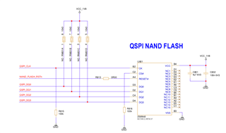
we are try to communicate winbond IC W25N02JWTBIF.
bellow is connection Image but we modify it. As-
H21---> ospi cs2
H24--->OSPI0_CLK
E25--->OSPI0_D0
G24--->OSPI0_D1
F25--->OSPI0_D2
F24--->OSPI0_D3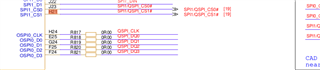
my DTS is:
&main_pmx0 {
ospi0_pins_default: ospi0-pins-default {
pinctrl-single,pins = <
AM62X_IOPAD(0x000, PIN_OUTPUT, 0) /* (H24) OSPI0_CLK */
AM62X_IOPAD(0x0034, PIN_OUTPUT, 0) /* (H21) OSPI0_CSn2 */
AM62X_IOPAD(0x00c, PIN_INPUT, 0) /* (E25) OSPI0_D0 */
AM62X_IOPAD(0x010, PIN_INPUT, 0) /* (G24) OSPI0_D1 */
AM62X_IOPAD(0x014, PIN_INPUT, 0) /* (F25) OSPI0_D2 */
AM62X_IOPAD(0x018, PIN_INPUT, 0) /* (F24) OSPI0_D3 */
>;
};
}
&ospi0 {
    flash@0 {
        compatible = "winbond,W25N01GV","spi-nand";
        reg = <0x0>;
        spi-tx-bus-width = <1>;
        spi-rx-bus-width = <4>;
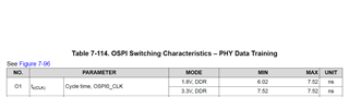
spi-max-frequency = <25000000>;
cdns,tshsl-ns = <60>;
cdns,tsd2d-ns = <60>;
cdns,tchsh-ns = <60>;
cdns,tslch-ns = <60>;
cdns,read-delay = <4>;
cdns,phy-mode;
partitions {
compatible = "fixed-partitions";
#address-cells = <1>;
#size-cells = <1>;
partition@0 {
label = "ospi.tiboot3";
reg = <0x0 0x80000>;
};
partition@80000 {
label = "ospi.tispl";
reg = <0x80000 0x200000>;
};
partition@280000 {
label = "ospi.u-boot";
reg = <0x280000 0x400000>;
};
partition@680000 {
label = "ospi.env";
reg = <0x680000 0x40000>;
};
partition@6c0000 {
label = "ospi.env.backup";
reg = <0x6c0000 0x40000>;
};
partition@800000 {
label = "ospi.rootfs";
reg = <0x800000 0x37c0000>;
};
partition@3fc0000 {
label = "ospi.phypattern";
reg = <0x3fc0000 0x40000>;
};
};
};
};
my configuration flag is
CONFIG_MTD_NAND_PLATFORM=y
CONFIG_MTD_NAND_CADENCE=y
CONFIG_COMPILE_TEST=y
CONFIG_ARM_BRCMSTB_AVS_CPUFREQ=y
CONFIG_ARM_SCMI_POWER_DOMAIN=y
CONFIG_ARM_SCPI_POWER_DOMAIN=y
CONFIG_MTD_SPEAR_SMI=y
CONFIG_MTD_NAND_ECC_SW_HAMMING_SMC=y
CONFIG_MTD_NAND_AMS_DELTA=y
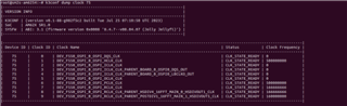
but I get error:
[ 1.781660] spi-nand: probe of spi0.0 failed with error -110.
Please let me know where i miss.
Thank you,
Chintan kothari