This thread has been locked.

If you have a related question, please click the "Ask a related question" button in the top right corner. The newly created question will be automatically linked to this question.

LP-AM263: receive of data from FSI-interface (loopback-mode, DMA) in debug mode does never finish

Part Number: LP-AM263

Hello, 

I'm testing the FSI-interface in DMA-mode. For this, I've imported the example (FSI in loopbackmode, DMA, nortos) from SDK-version 8.5.24. We use the Code Composer Studio version 12.2.
The example runs correct, if do debugging in single step mode. The data are transmitted and received correctly.

But if I run the example from main function start to a breakpoint (no single step operation) after the semaphores, waiting for the receive of the looped backed data from FSI, the software is looping endless in the semaphore, waiting for the RX of FSI.

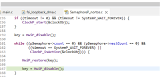
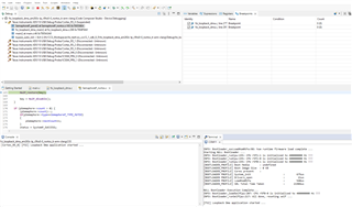
The breakpoint is set here:

The software is hanging in the RX semaphore:

We tried the example also with SBL from the external flash. In this constellation, the example is running without any problems (in release and debug compile).
A collegue of me has the problem on his evaluation board also.

The problem is 100% reproducable.

What can be the problem here? Please help.

  • Hi

    The ticket is assigned to expert

    Thanks & regards

    Sri Vidya

  • Hi Jo,

    I cannot reproduce your reported issue with the following steps:

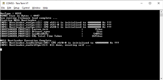
    1. Initialize the AM263x CC. The UART will display the following:

    2. Load the program. 

    3. Set the breakpoint after the semaphores

    4. Run the program and reach the breakpoint

    5 Continue to run the program.

    The program finishes properly.

    Your reported issue only happens when I re-load and run the program immediately after the first run without initializing the AM263x CC. I think it may be caused by the resource (like EDMA) may not be released completely.

    You may need to flash the SBL_NULL into the QSPI flash to initialize the AM263x CC properly before running the program again.

    Please refer to the URL for details on how to initialize the AM263x CC: AM263x MCU+ SDK: Additional Details

    Best regards,

    Ming

  • Hello Ming,

    I have some further questions:

    - what SDK-version did you use?
    - did you test also with LP-board? I have no CC-board, I have only a LP-board

    Best Regards,

    Jo Scho

  • Hello Ming,

    here a some supplements for this problem:

    I tried with the SBL-NULL configuration, as you mentioned in your last reply.
    (Code Composer Studio 12.1, LP-Board, SDK 8.5.0.24 --> we never reach the second breakpoint here, the firmware waits endless for the RX semaphore (only in debug mode)

    I tried now the new SDK version 8.6.0.34 with CCS 12.1 and CCS 12.2 --> the problem is not existing with SDK 8.6.0.34 for both CCS versions

    We would like to understand the problem, to be save in further developement.

    Best regards

    Jo Scho

  • Hi Jo,

    I used the CCS 12.2.0 and the MCU+ SDK 08.05.00.24. I have tried 

    fsi_loopback_dma_am263x-lp_r5fss0-0_nortos_ti-arm-clang (both Debug and Release) on AM263x LP

    fsi_loopback_dma_am263x-cc_r5fss0-0_nortos_ti-arm-clang (both Debug and Release) on AM263x CC

    Oh, I recall I made some changes in the EDMA_open to change the Hwi trigger from pulse to level for MCU+ SDK 08.05.00.24. That is probably why my example works. All those changes are included in the 08.06.00.34, so that is why the example works for 08.06.00.34.

    Best regards,

    Ming

  • Hello Ming,

    thank you very much four your answer. I just have one question for understanding.


    You said in your last answer, that you have changed the Hwi trigger from pulse to level mode.
    I tried to understand the modification in the SDK from version 8.5 to 8.6. I recognized the change in the file "source/drivers/edma/v0/edma.c"

    The flag "isPulse is set to 1 here, now. In SDK version 8.5 the flag is 0.

    The comment of the flag variable indicates another behaviour. (file HwiP.h,  0 == level interrupt, 1== pulse interrupt)

    The register description of AM263x would also suggest that setting a 1 means pulse mode.

    Are my assumptions wrong? Or is the pulse mode the correct mode, to be used for correct behaviour?

    Best regards,

    Jo Scho

  • Hi Jo,

    You are correct. It was set to level trigger previously and it should have been set to pulse trigger. I mis-spoke in last post.

    Best regards,

    Ming

  • Hi Ming,

    your answer solved the problem, but I discussed the problem and the solution with my collegues yesterday.

    We do not really understand, the change of level to pulse or in detail, the effect of the change and why it functions with pulse mode now.
    In SDK 8.5 there was level mode for Hwi trigger, in SDK 8.6 this is changed to pulse mode.

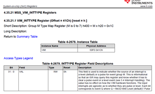
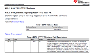
    In the technical reference manual spruj42c.pdf there is the description of the interrupt type register, this is the register, where the pulse/level information is configured to.

    The description says, that the value, set to this register has no effect on how the VIM hardware function. Due to that description, we tried to understand 
    that with pulse mode the debugging of the FSI example functions properly and with level mode, debugging fails.

    In our understanding, the register is only a buffer, whether the firmware should make a level or pulse evaluation and has no hardware effect. Is this correct?

    In this context, we searched for all places in the source code where the function HwiP_isPulse() is called.
    The function is used in the Modul HwiP_arm7vr_handlers_nortos.c in the functions HwiP_fiq_handler() and HwiP_irq_handler_c().

    EDMA does not use the FIQ-Handler, it uses the normal IRQ-Handler, we think.

    Our problem at the moment is, that we do not really understand the source code of the function HwiP_irq_handler_c:

    In case of pulse mode, the pending interrupt is cleared before the service routine is executed, in level mode, the clear of a pending IRQ is after the ISR-execution. But in our understanding (VIM hardware is, due to the reference manual, not influenced by the pulse or level mode configuraion) this change no makes no difference for the FSI example.

    Perhaps you can give us some more information or explain us, why it functions in pulse mode, but not in level mode.

    Best regards

    Jo Scho


  • Hi Jo,

    I agree that setting the VIM_INT_TYPE is only informative for the HwiP_irq_handler_c().

    I think the reason it clears interrupt at different places (before or after calling the ISR) is because that for pulse interrupt, it will not be re-generated (set bit in VIM_STS) after clearing. Whereas for level interrupt, it will be re-generated again after clearing, therefore, early clear is not effective.

    Best regards,

    Ming