This thread has been locked.

If you have a related question, please click the "Ask a related question" button in the top right corner. The newly created question will be automatically linked to this question.

AM5718: booting issue

Part Number: AM5718
Other Parts Discussed in Thread: TMDXIDK5718

hi,

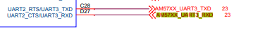
I am using am5718 6.03.00.108 sdk using linux. we created boot files which works perfectly for evolution and when we try with custom board through uart3 we didn't get any data. We used MT41K256M16LY ddr3l and using only 16 data lines insted of 32 data lines. I had done the necessary changes for that as mentioned in

https://e2e.ti.com/support/processors-group/processors/f/processors-forum/652269/linux-dra756-does-dra756-support-one-bank-with-16bit-data-bus-using-512mb-size

and updated as per this still i don't get any data in uart3.

regards,

Bhardwaj.

  • Hello Bhardwaj,

    Can you you please provide a diff of what you changed on the Linux SDK so we can get a better picture of your issue?

    -Josue

  • hi josue,

    I had changed two structures in board.c file found at u-boot directory /board/am57xx


    static const struct emif_regs am571x_emif1_ddr3_666mhz_emif_regs = {
        .sdram_config_init        = 0x61867332,  //0x61863332
        .sdram_config            = 0x61867332,
        .sdram_config2            = 0x08000000,
        .ref_ctrl            = 0x0000514d,
        .ref_ctrl_final            = 0x0000144a,
        .sdram_tim1            = 0xd333887c,
        .sdram_tim2            = 0x30b37fe3,
        .sdram_tim3            = 0x409f8ad8,
        .read_idle_ctrl            = 0x00050000,
        .zq_config            = 0x5007190b,
        .temp_alert_config        = 0x00000000,
        .emif_ddr_phy_ctlr_1_init    = 0x0024400f,
        .emif_ddr_phy_ctlr_1        = 0x0e24400f,
        .emif_ddr_ext_phy_ctrl_1    = 0x10040100,
        .emif_ddr_ext_phy_ctrl_2    = 0x00910091,
        .emif_ddr_ext_phy_ctrl_3    = 0x00950095,
        .emif_ddr_ext_phy_ctrl_4    = 0x009b009b,
        .emif_ddr_ext_phy_ctrl_5    = 0x009e009e,
        .emif_rd_wr_lvl_rmp_win        = 0x00000000,
        .emif_rd_wr_lvl_rmp_ctl        = 0x80000000,
        .emif_rd_wr_lvl_ctl        = 0x00000000,
        .emif_rd_wr_exec_thresh        = 0x00000305
    };

    static const struct dmm_lisa_map_regs am571x_idk_lisa_regs = {
        .dmm_lisa_map_3 = 0x80540100,//0x80640100
        .is_ma_present  = 0x1
    };

    After that i have created the new files for u-boot.img,u-boot.bin and MLO. I have observed that the data is coming on single line i.e, only on mmc_d0 pin and clock is 15mhz where as evolution board clock is 48mhz on mmc_clk.

    bhardwaj kotha.

  • hi,

    I had replied to your question.If possible can you reply as soon as.

    thankyou,

    Bhardwaj

  • Hello Bhardwaj,

    On your custom board, did you use the same ball pins as we did on the AM57 evm? Can you tell me what evaluation board you have? TMDXIDK5718?

    This is how they are connected on TMDXIDK5718

    C28 for TX and D27 for RX

    If they are different, we would need to change the pinmux.

    -Josue

  • hi,

    In our custom board we have different uart3 lines i.e, AB3 for RX and AA4 for TX. I have updated the related pinmux which is found in u-boot directory /board/ti/am57xx/mux_data.h file.  I had commented the lines for uart3 using c28 and d27 and added for AB3 and AA4 from 1193 line.

    const struct pad_conf_entry early_padconf[] = {
        //{UART2_CTSN, (M2 | PIN_INPUT_SLEW)},    /* uart2_ctsn.uart3_rxd */
        //{UART2_RTSN, (M1 | PIN_INPUT_SLEW)},    /* uart2_rtsn.uart3_txd */
        {I2C1_SDA, (PIN_INPUT_PULLUP | M0)},    /* I2C1_SDA */
        {I2C1_SCL, (PIN_INPUT_PULLUP | M0)},    /* I2C1_SCL */
        {MCASP5_AXR0, (M4 | PIN_INPUT_SLEW)},    /* mcasp5_axr0.uart3_rxd */
        {MCASP5_AXR1, (M4 | PIN_INPUT_SLEW)},

        /* BeagleBone AI: Debug UART */
        {UART1_RXD, (M0 | PIN_INPUT_PULLDOWN | SLEWCONTROL)},    /* uart1_rxd.uart1_rxd */
        {UART1_TXD, (M0 | PIN_OUTPUT_PULLDOWN | SLEWCONTROL)},    /* uart1_txd.uart1_txd */
    };

    Thanks and regards,

    Bhardwaj

  • hi,

    yes, i am using TMDXIDK5718.

    regards

    bhardwaj

  • Hi Bhardwaj,

    Are you able to share your mux file to review that there are no pinmux conflicts?

    -Josue

  • hi,

    can you provide your mail id, i will share that to your mail.

    bhardwaj

  • Hi,

    I am using the same pinmux file which is present in tisdk06.03.00.106/board support/u-boot/board/ti/am57xx/muxdata.h file with the changes above mentioned in ddr and uart3. We are using the same lines for ddr and mmc1(SD card) from sitara am5718.

    Thanks

    Bhardwaj

  • Hi Bhardwaj,

    In the file /board/ti/am57xx/mux_data.h, 

       //{UART2_CTSN, (M2 | PIN_INPUT_SLEW)},    /* uart2_ctsn.uart3_rxd */
        //{UART2_RTSN, (M1 | PIN_INPUT_SLEW)},    /* uart2_rtsn.uart3_txd */

    this is for UART2. Are you sure you are changing the pin mux to the correct lines?

    See lines 1002-1003 in mux_data.h:

    Have you tried using the PinMux tool on www.ti.com/.../SYSCONFIG

  • hi,

    //{UART2_CTSN, (M2 | PIN_INPUT_SLEW)},    /* uart2_ctsn.uart3_rxd */
        //{UART2_RTSN, (M1 | PIN_INPUT_SLEW)},    /* uart2_rtsn.uart3_txd */

    These lines are already present in pinmux for am5718 idk which is for uart3. we are also using the uart3 only, but in my custom board the pins are different for uart3. The pins we are using are

    {MCASP5_AXR0, (M4 | PIN_INPUT_SLEW)},    /* mcasp5_axr0.uart3_rxd */
    {MCASP5_AXR1, (M4 | PIN_INPUT_SLEW)},    /*mcasp5_axr0.uart3_txd*/

    These pins will generate the boot logs on serial communication in minicom.

    can you tell me my changes for uart3 and ddr are correct. if possible can you communicate with your technical team. 

     Thanks

    Bhardwaj

  • Bhardwaj,

    I understand.

    How do you know that the device has come up? Do you have JTAG?

    -Josue

  • hi,

    Sorry for late reply.Yes, i have jtag.No, i don't know.

    But i tried to debug the u-boot through through jtag by loading  into memory (u-boot-spl.bin) and then i load symbols(u-boot-spl) into am5718 custom board.

    After loading symbols i had debug by using step over by viewing in disassembly it is moving step by step till the last address in save_boot_params_ret();  and sometimes at switch_to_hypervisor_ret() in disassembly, then again when i do step over it is not going to next step it holds there only and when suspend the button on menu it produces the following error.

    CortexA15_0: Trouble Halting Target CPU: (Error -1323 @ 0x403028CD) Device failed to enter debug/halt mode because pipeline is stalled. Power-cycle the board. If error persists, confirm configuration and/or try more reliable JTAG settings (e.g. lower TCLK). (Emulation package 9.7.0.00213)

    for switch_to_hypervisor_ret();

    /resized-image/__size/720x240/__key/communityserver-discussions-components-files/791/Screenshot-from-2023_2D00_06_2D00_05-21_2D00_34_2D00_31.png
      for save_boot_params_ret();

    i have another question

    In my board mmc1_sdcd pin is continuously high. If i pulldown in pinmux whether it is correct to do?

    Thanks and regards

    bhardwaj

  • hi,

    How do you know that the device has come up?

    By using scope i have monitored the mmc_data lines that some data is coming for some milli seconds on only mmc_data0 pin till that clock also coming but after that clock becomes zero and there is no data on all data lines. if any possible cases to test please tell me.

    Thankyou

    Bhardwaj.

  • hi Bhardwaj,

    You should be able to connect to the A15 core and probe the memory. I will be consulting internally and we will get back to you as soon as I hear back.

    -Josue

  • Bhardwaj,

    By using scope i have monitored the mmc_data lines that some data is coming for some milli seconds on only mmc_data0 pin till that clock also coming but after that clock becomes zero and there is no data on all data lines

    I am inferring that you are trying to boot from SD card, is that right? Does your board have the capability of other boot modes? 

    Can we try booting with no-boot mode and loading a GEL file to initialize the A15 core via CCS?

  • hi,

    yes, i am able to load the gel files into a15 core and i had verified by toggling the gpio pin. Then i had tried with loading the u-boot code into core a15 but produces the following error

    CortexA15_0: Trouble Halting Target CPU: (Error -1323 @ 0x403028CD) Device failed to enter debug/halt mode because pipeline is stalled. Power-cycle the board. If error persists, confirm configuration and/or try more reliable JTAG settings (e.g. lower TCLK). (Emulation package 9.7.0.00213)

    i am unable to boot the board. Can u please guide me why it is happening like that?

    Thanks and regards,

    Bhardwaj.

  • Hello Bhardwaj,

    Are you able to get traces around the crash? We need more information around this to determine whether this is a software/memory issue or even a hardware issue.

    a couple of more questions?

    • Is this  the only board you have? 
    • If there is more, has this happened with other boards?
    • Did you base the design of  your custom board on a TI EVM, if so which one?
  • hi josue,

    The issue is solved after doing system reset, but i need to do  every time while debugging u-boot. Is there any permanent solution for that, if i don't do system reset the pipeline error(Device failed to enter debug/halt mode because pipeline is stalled) is coming on console.

    1) we have only one board.

    3) Our board design is based on AM5718 IDK.

     I got an another problem.

    In am5718 idk C28 and D27 are pins given for uart3 whereas AA4,AB3 pins for uart3 in custom board. So, i modified the pinmux.h file by removing

    uart2_ctsn and uart2_rtsn, added  MCASP5_AXR0 and MCASP5_AXR1 for uart3.

    const struct pad_conf_entry early_padconf[] = {
     line 1194  -- //{UART2_CTSN, (M2 | PIN_INPUT_SLEW)},    /* uart2_ctsn.uart3_rxd */ 
     line 1195  -- //{UART2_RTSN, (M1 | PIN_INPUT_SLEW)},    /* uart2_rtsn.uart3_txd */
        ++ {MCASP5_AXR0, (M4 | PIN_INPUT)},    /* mcasp5_axr0.uart3_rxd */
        ++ {MCASP5_AXR1, (M4 | PIN_OUTPUT)},    /* mcasp5_axr1.uart3_txd */
             {I2C1_SDA, (PIN_INPUT_PULLUP | M0)},    /* I2C1_SDA */
             {I2C1_SCL, (PIN_INPUT_PULLUP | M0)},    /* I2C1_SCL */

    }

    and also modified in

    const struct pad_conf_entry core_padconf_array_essential_am571x_idk[]{

    line  1060--  //{MCASP5_AXR0, (M4 | PIN_INPUT)},    /* mcasp5_axr0.uart3_rxd */
    line 1061-- //{MCASP5_AXR1, (M4 | PIN_OUTPUT)},    /* mcasp5_axr1.uart3_txd */

    }

    after modifying i clean the u-boot and started making am57xx_evm_config,spl/u-boot-spl and u-boot.bin as mentioned in video series for debugging u-boot. Debugging the u-boot through jtag, by load memory (u-boot-spl.bin) and then load symbols(u-boot-spl) into am5718 custom board, then it is coming to hang() function but no data is printing on minicom and I had verified by pointing on that pin that there is no data on scope. after pressing pause button on menu bar  it should print the following lines on minicom.

    U-Boot SPL 2019.01-g323d51410c-dirty (Jun 15 2023 - 17:07:24 +0530)          
    DRA722-GP ES2.0                                                              
    no pinctrl state for default mode                                            
    Card did not respond to voltage select!                                      
    Firmware loading failed                 
    SPL: failed to boot from all boot devices
    ### ERROR ### Please RESET the board ###

    Thanks

    bhardwaj.

  • Hi Bhardwaj,

    Do I understand you correctly:

    The issue is solved after doing system reset, but i need to do  every time while debugging u-boot. Is there any permanent solution for that, if i don't do system reset the pipeline error(Device failed to enter debug/halt mode because pipeline is stalled) is coming on console.

    Resetting the board solves the u-boot hang issue, but you still have no output via UART.

    Then, you made the pinmux changes, rebuilt your spl and u-boot binary, but then there is another hang in which you paused the core using CCS and you got the following output:

    U-Boot SPL 2019.01-g323d51410c-dirty (Jun 15 2023 - 17:07:24 +0530)          
    DRA722-GP ES2.0                                                              
    no pinctrl state for default mode                                            
    Card did not respond to voltage select!                                      
    Firmware loading failed                 
    SPL: failed to boot from all boot devices
    ### ERROR ### Please RESET the board ###

    Can you please clarify, this is the output you are expecting or this is the output that is produced?

    Was the u-boot initialization  on your console on CCS or on minicom?

    -Josue

  • In addition, Are you disabling the GEL files when trying to debug U-boot?

    -Josue

  • hi,

    Yes, i am disabling the gel files while debugging u-boot.

    bhardwaj

  • Hi Bhardwaj,

    Could you please answer my previous questions so I can get a better understanding?

    Regards,

    -Josue

  • hi,

    U-Boot SPL 2019.01-g323d51410c-dirty (Jun 15 2023 - 17:07:24 +0530)          
    DRA722-GP ES2.0                                                              
    no pinctrl state for default mode                                            
    Card did not respond to voltage select!                                      
    Firmware loading failed                 
    SPL: failed to boot from all boot devices
    ### ERROR ### Please RESET the board ###

    These should be the output on terminal, but after making changes regarding uart3 nothing is displaying and i had verified by probing in scope.

    I had added 2 lines by removing existing lines

    const struct pad_conf_entry early_padconf[] = {
     line 1194  -- //{UART2_CTSN, (M2 | PIN_INPUT_SLEW)},    /* uart2_ctsn.uart3_rxd */ 
     line 1195  -- //{UART2_RTSN, (M1 | PIN_INPUT_SLEW)},    /* uart2_rtsn.uart3_txd */
        ++ {MCASP5_AXR0, (M4 | PIN_INPUT)},    /* mcasp5_axr0.uart3_rxd */
        ++ {MCASP5_AXR1, (M4 | PIN_OUTPUT)},    /* mcasp5_axr1.uart3_txd */
             {I2C1_SDA, (PIN_INPUT_PULLUP | M0)},    /* I2C1_SDA */
             {I2C1_SCL, (PIN_INPUT_PULLUP | M0)},    /* I2C1_SCL */

    }

    Why i am unable to get the prints on terminal?

    answers for your questions.

    1) Resetting the board solves the u-boot hang issue, but you still have no output via UART?

       Yes.

    2) Can you please clarify, this is the output you are expecting or this is the output that is produced?

    i am expecting that output.

    3) Was the u-boot initialization  on your console on CCS or on minicom?

    i am debugging the u-boot using ccs following this process mentioned in am335x sdk

    https://software-dl.ti.com/processor-sdk-linux/esd/AM335X/08_02_00_24/exports/docs/linux/Foundational_Components/U-Boot/Apps-Load-in-CCS.html

    thanks and regards,

    bhardwaj.

  • hi,

    I am unable to use the uart3 pins for serial debugging.

    u-boot directory/board/ti/am57xx/muxdata.h

    const struct pad_conf_entry early_padconf[] = {

        ++ {MCASP5_AXR0, (M4 | PIN_INPUT)},    /* mcasp5_axr0.uart3_rxd */
        ++ {MCASP5_AXR1, (M4 | PIN_OUTPUT)},    /* mcasp5_axr1.uart3_txd */

    }

    I have answered for your questions in last post. please provide some solution for that ASAP and i had struck there for last few days.

    Thanks,

    Bhardwaj

  • Hello bhardwaj,

    I am consulting internally again and will respond as I get feedback.

    Accidentally pressed on the resolved button. .. I apologize for that.

    Josue

  • Hello Bhardwaj,

    Can you read out the values of the pin mux registers from the CCS:

    0x4A00374C & 0x4A003750 register values respectively to confirm if indeed the mux is set up properly for the UART.

    - Keerthy 

  • hi,

    Sorry for the late response. As you said i had verified through debugging u-boot. The pinmux is done correctly.

    The values for the pinmux are:

    0x4A00374C    --   0x000C0004

    0x4A003750    --    0x00020004

    The modification in pinmux.h

        {MCASP5_AXR0, (M4 | PIN_INPUT_PULLDOWN | SLEWCONTROL)},    /* mcasp5_axr0.uart3_rxd */
        {MCASP5_AXR1, (M4 | PIN_OUTPUT_PULLUP)},                               /* mcasp5_axr1.uart3_txd *

    Thanks & regards,

    Bhardwaj.

  • Hello Bhardwaj,

    After reviewing your CTRL_CORE_PAD_MCASP5 register contents, the changes are not being registered even though the MUXMODE register is correct for both.

    For CTRL_CORE_PAD_MCASP5_AXR1 PIN_OUTPUT_PULLUP should make bit 17 a 0b1 and it is not.

    For CTRL_CORE_PAD_MCASP5_AXR0: 

    {MCASP5_AXR0, (M4 | PIN_INPUT_PULLDOWN | SLEWCONTROL)

    PIN_INPUT_PULLDOWN should be setting bit 18 to 0b1 = Receive mode is enabled but it is not.

    I think this might be why it is not working, INPUTENABLE  should be a 1 for the RX pin.

    Please let me know if this helps,

    Regards,

    Josue