This thread has been locked.

If you have a related question, please click the "Ask a related question" button in the top right corner. The newly created question will be automatically linked to this question.

PROCESSOR-SDK-AM62X: LVDS not working...

Part Number: PROCESSOR-SDK-AM62X

Hi TI Team,

We are using TI am6254 processor for our custom board and want to enable display support via LVDS to HDMI. Here we used same pins setup of EVM for LVDS which used as OLDI interface in TI am6254 EVM.

Hardware setup:
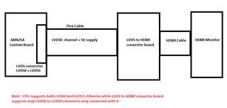
Device Tree Changes:

The Below device tree changes I have made as of now. Please correct me  what things I need to add here.

&dss {

        status = "okay";

        pinctrl-names = "default";

        pinctrl-0 = <&main_oldi0_pins_default>;

};

&dss_ports {

        #address-cells = <1>;

        #size-cells = <0>;

        status = "okay";

/*Here I skipped the ports as I connected hdmi bridge/converter which has preloaded driver in it

 We have commented out this red highlighted area*/

        /* VP1: LVDS Output (OLDI TX 0) */

        port@0 {

                reg = <0>;

                oldi_out0: endpoint {

                        remote-endpoint = <&lcd_in0>;

                };

        };

        /* VP1: LVDS Output (OLDI TX 1) */

        port@2 {

                reg = <2>;

                oldi_out1: endpoint {

                        remote-endpoint = <&lcd_in1>;

                };

        };

};

        main_oldi0_pins_default: main-oldi0-pins-default {

                pinctrl-single,pins = <

                        AM62X_IOPAD(0x0260, PIN_OUTPUT, 0) /* (AA5) OLDI0_A0N */

                        AM62X_IOPAD(0x025c, PIN_OUTPUT, 0) /* (Y6) OLDI0_A0P */

                        AM62X_IOPAD(0x0268, PIN_OUTPUT, 0) /* (AD3) OLDI0_A1N */

                        AM62X_IOPAD(0x0264, PIN_OUTPUT, 0) /* (AB4) OLDI0_A1P */

                        AM62X_IOPAD(0x0270, PIN_OUTPUT, 0) /* (Y8) OLDI0_A2N */

                        AM62X_IOPAD(0x026c, PIN_OUTPUT, 0) /* (AA8) OLDI0_A2P */

                        AM62X_IOPAD(0x0278, PIN_OUTPUT, 0) /* (AB6) OLDI0_A3N */

                        AM62X_IOPAD(0x0274, PIN_OUTPUT, 0) /* (AA7) OLDI0_A3P */

                        AM62X_IOPAD(0x0280, PIN_OUTPUT, 0) /* (AC6) OLDI0_A4N */

                        AM62X_IOPAD(0x027c, PIN_OUTPUT, 0) /* (AC5) OLDI0_A4P */

                        AM62X_IOPAD(0x0288, PIN_OUTPUT, 0) /* (AE5) OLDI0_A5N */

                        AM62X_IOPAD(0x0284, PIN_OUTPUT, 0) /* (AD6) OLDI0_A5P */

                        AM62X_IOPAD(0x0290, PIN_OUTPUT, 0) /* (AE6) OLDI0_A6N */

                        AM62X_IOPAD(0x028c, PIN_OUTPUT, 0) /* (AD7) OLDI0_A6P */

                        AM62X_IOPAD(0x0298, PIN_OUTPUT, 0) /* (AD8) OLDI0_A7N */

                        AM62X_IOPAD(0x0294, PIN_OUTPUT, 0) /* (AE7) OLDI0_A7P */

                        AM62X_IOPAD(0x02a0, PIN_OUTPUT, 0) /* (AD4) OLDI0_CLK0N */

                        AM62X_IOPAD(0x029c, PIN_OUTPUT, 0) /* (AE3) OLDI0_CLK0P */

                        AM62X_IOPAD(0x02a8, PIN_OUTPUT, 0) /* (AE4) OLDI0_CLK1N */

                        AM62X_IOPAD(0x02a4, PIN_OUTPUT, 0) /* (AD5) OLDI0_CLK1P */

                >;

        };

With above all configuration, We are unable see TI logo and other qt examples in HDMI  Monitor. Please correct us if anything is missing in above configurations. 

As I have mentioned earlier that We have added LVDS to HDMI bridge / converter in between LVDS to HDMI monitor. So Do We require to add any device tree changes for same ? If yes then please suggest us the software changes. Also We did not get any signals on LVDS port of CPU.

Thanks,

Maulik

  • Hello Maulik,

    Our recommendation is to keep the LCD dtbo as the TI EVM and change the timing parameter based on the bridge requirements: https://git.ti.com/cgit/ti-linux-kernel/ti-linux-kernel/tree/drivers/gpu/drm/panel/panel-simple.c?h=ti-linux-5.10.y#n2821 

    Here is the section that you would need to change:

    	.clock = 150275,
    	.hdisplay = 1920,
    	.hsync_start = 1920 + 32,
    	.hsync_end = 1920 + 32 + 52,
    	.htotal = 1920 + 32 + 52 + 24,
    	.vdisplay = 1200,
    	.vsync_start = 1200 + 24,
    	.vsync_end = 1200 + 24 + 8,
    	.vtotal = 1200 + 24 + 8 + 3,


    Regards,

    Krunal

  • Hi Krunal,

    Thanks for response. 

    As I mentioned in my earlier post that we are using OLDI interface of DSS for the LVDS display. And Please note that We are not using RGB interface of DSS (eg. VOUT* Hsync, VSync, etc pins) but in place of RGB pins we are using alternate functions other than display.

    Test 1) TI EVM DTBO file

    I tried to use EVM dtbo - k3-am625-sk-oldi-panel.dtbo but I am facing some issue while booting the kernel. Here below I have attached error logs for reference. I verified that dtbo file is present in card.

    => setenv name_overlays k3-am625-sk-oldi-panel.dtbo

    => saveenv

    Saving Environment to MMC... Writing to MMC(0)... MMC: block number 0x3500 exceeds max(0x2000)

    failed

    Failed (1)

    => boot

    switch to partitions #0, OK

    mmc1 is current device

    SD/MMC found on device 1

    Failed to load 'boot.scr'

    1830 bytes read in 3 ms (595.7 KiB/s)

    Loaded env from uEnv.txt

    Importing environment from mmc1 ...

    Running uenvcmd ...

    1 bytes read in 2 ms (0 Bytes/s)

    Already setup.

    21256704 bytes read in 884 ms (22.9 MiB/s)

    62482 bytes read in 6 ms (9.9 MiB/s)

    1330 bytes read in 4 ms (324.2 KiB/s)

    failed on fdt_overlay_apply(): FDT_ERR_NOTFOUND

    979 bytes read in 3 ms (318.4 KiB/s)

    failed on fdt_overlay_apply(): FDT_ERR_BADMAGIC

    base fdt does did not have a /__symbols__ node

    make sure you've compiled with -@

    2478 bytes read in 3 ms (806.6 KiB/s)

    failed on fdt_overlay_apply(): FDT_ERR_BADMAGIC

    base fdt does did not have a /__symbols__ node

    make sure you've compiled with -@

    ERROR: Did not find a cmdline Flattened Device Tree

    Could not find a valid device tree


    Test 2)As We were not successful for the LVDS to HDMI testing, So We tried to test single link 18bit LVDS display directly over the dual link OLDI interface of the CPU. We have  AMA-070A04-DU2511-G010 display with us.

    We modified display node as per our LVDS  panel and currently using panel-simple driver for the same. Here below I attached device tree changes of our custom board based on am6254 processor for your reference purpose.

    We also tested single link lvds using below code but we did't get any signal over oscilloscope regarding LVDS interface from CPU.

    / {
    ...

            display0 {
                    compatible = "rocktech,rk101ii01d-ct";
                    backlight = <&lcd_bl>;
                    pinctrl-names = "default";
                    pinctrl-0 = <&lvds_enable_pin>;

                    port {
                            lcd_in0: endpoint {
                                    remote-endpoint = <&oldi_out0>;
                            };
                    };
            };
    ...
    };

    &dss {
            status = "okay";
    };

    &dss_ports {
            #address-cells = <1>;
            #size-cells = <0>;

            port@0 {
                    reg = <0>;

                    oldi_out0: endpoint {
                            remote-endpoint = <&lcd_in0>;
                    };
            };
    };

    Then, We tried dual link lvds same like TI EVM but result is still the same as single link. Here below I attached device tree changes. We also did not get /dev/fb0 node for display.

          
    	  panel {
                    label = "AMA-070A04-DU2511-G010";
                    status="okay";
                    compatible = "panel-simple";
    							data-mapping="jeida-18";
                    panel-timing {
                            clock-frequency = <25000000>;
                            hactive = <800>;
                            vactive = <480>;
                            hfront-porch = <8>;
                            hback-porch = <8>;
                            vback-porch = <8>;
                            vfront-porch = <8>;
                            hsync-len = <8>;
                            vsync-len = <4>;
                            hsync-active = <0>;
                            vsync-active = <0>;
                            de-active = <1>;
                            pixelclk-active = <0>;
                    };
    
                    port@0 {
                           dual-lvds-odd-pixels;
                           lcd_in0: endpoint {
                                   remote-endpoint = <&oldi_out0>;
                           };
                    };
    
                    port@1 {
                           dual-lvds-even-pixels;
                           lcd_in1: endpoint {
                                    remote-endpoint = <&oldi_out1>;
                           };
                    };
            };


    &dss {
            status = "okay";
    	pinctrl-names = "default";
            pinctrl-0 = <&main_oldi0_pins_default>;
    };
    
    &dss_ports {
            #address-cells = <1>;
            #size-cells = <0>;
    	status = "okay";
    
    	port@0 {
    		reg = <0>;
    		oldi_out0: endpoint {
    			remote-endpoint = <&lcd_in0>;
    		};
    	};
    
    	port@2 {
    		reg = <2>;
    		oldi_out1: endpoint {
    			remote-endpoint = <&lcd_in1>;
    		};
    	};
    
    };

    We would like to know why LVDS signals are not generated from CPU? 

    Thanks,

    Maulik

  • Hi Maulik,

    Okay, let's do a simple experiment since you have a TI EVM. I am not sure which image you are using but download the latest from the following link: tisdk-default-image-am62xx-evm.wic.xz. Flash the SD card using balena and modify the uEnv.txt file with the following "name_overlays=k3-am625-sk-oldi-panel.dtbo". Boot the EVM and don't worry about connecting a LVDS panel. Upon boot, Weston would be running in the background, kill weston (/etc/init.d/weston stop) and run kmstest. On the console, it would print LVDS timing information and then probe the CLK signals. I have tested the above on SK EVM several times and it should work without any issues on your setup as well. 

    Regards,
    Krunal

  • Thank you Krunal for the answer.