This thread has been locked.

If you have a related question, please click the "Ask a related question" button in the top right corner. The newly created question will be automatically linked to this question.

AM3352: Boot issue

Part Number: AM3352

Hi,

We are currently experiencing a problem with some field units. Our design uses the AM3352BZCZ100 in conjunction with the TPS65217C (PMIC) for power management. The problem we have is that some field units are getting into a non-functional state for which the only way to recover from, is to do a complete power shutdown (i.e. remove the battery, remove the power connected to the AC pin of the PMIC and then reapply power). We use the main power (connected to the AC pin) exclusively for running operation and we use the battery only for time keeping if the system ever goes into a PMIC SLEEP state.

What we could measure/observe on the units that were returned to us is the following:

  • External RTC is not running (we measure 1.8V on the XTALIN pin).
  • All power rails coming from the PMIC are active and at the default values for the TPS65217C.
  • Toggling the state of the WARMRSTn pin (through a push button switch) does not have any effect.
  • No activity on the console port (UART0 interface) connected via FTDI.


The above information leads us to believe that we could be stuck in the bootup sequence of the CPU. This hypothesis is based on the following:

  • In our application, we use an external 32.768kHz. By default, upon bootup the AM3352 uses the internal 32kHz (derived from internal PLL) for the RTC clock source and the usage of the external source is set during boot.
  • Our application uses the AM3352 in Nitro mode (1GHz). This requires that the VDD_MPU be set to 1.325V. This is again set during boot via I2C communication between the AM3352 and the PMIC.
  • WARMRSTn is ineffective to reinitialize the unit as it seems that no boot image has been found yet.

We are currently concerned that we could have an issue with the values loaded in the SYSBOOT device lists. We think that improper values might be loaded in the CONTROL_STATUS register for the boot device list which would cause the system to try and find a boot image in a device list that does not contain anything bootable. Unfortunately, since there is no activity on the system at that point, we cannot query the CONTROL_STATUS register to see which values might be loaded.

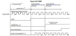
One question that we have concerns the SYSBOOT latching sequence. In numerous sections of the reference manual, it is stated that the “final” SYSBOOT values are latched at the last rising edge of the PWRONRSTn. However, we can read the following in section 8.1.7.3.2 of the technical reference manual:

“PORz pin at chip boundary gets asserted (goes low). Note: The state of nRESETIN_OUT during PORz assertion should be a don’t care, it should not affect PORz (only implication is if they are both asserted and nRESETIN_OUT is deasserted after PORz you will get re-latching of boot config pins and may see warm nRESETIN_OUT flag set in PRCM versus POR).”

Could you please provide some explanation concerning the highlighted text? From what we can see in the timing diagram of figure 8.23, it seems to be a standard behavior to have the nRESETIN_OUT (WARMRSTn external pin) de-asserted after the PORz (PWRONRSTn external pin):


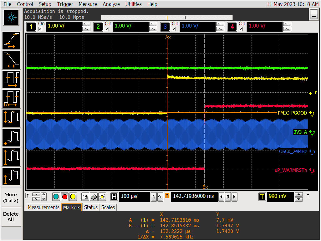
We can also observe this sort of timing on one of our working units:

Could you please help us understand the re-latching condition mentioned in the reference manual (listed above) and provide any other information/questions that could help us investigate this issue further?

Thank you.

  • Hi Marc, sorry for the delay here.

    Do you have JTAG access on the returned boards?  This would help be able to examine the CONTROL_STATUS register to see if it truly is getting latched incorrectly

    I think the highlighted text is just referring to the instance where both POR and nRESET_INOUT are both asserted.  In this case, the boot pins will get relatched since PORz was toggled.  If you are just toggling nRESET_INOUT, then the boot pins will not get relatched, and the original boot order should occur. 

    One thing i can think of is that these failing units may be possibly getting a inadvertent POR asserted, which may be latching in a bad SYSBOOT value.  In this case, your suspicion would be correct since a WARTRST would attempt to boot from a source that was not intended.  To test this on a failing unit, you can probe some signals to see if the ROM is executing.  I'm not sure what your boot list is, but for example, you can check to see if CS is toggling if you are booting from NAND, or check a clock signal on a boot interface that uses a clock.  Which boot sequence are you using? 

    Regards,

    James

  • Hi James,

    Thanks for the feedback. We do have access to JTAG in our design and it could effectively be used to read back the CONTROL_STATUS register to verify the SYSBOOT value(s).

    Last time I had a failing unit, I was getting to probe around to see if the ROM code was cycling through the boot list devices, but unfortunately the unit eventually shutdown and I was unable to recreate the issue. I will surely be doing that (and JTAG access) the next time I get my hands on a failing unit.

    My boot list is '11100b' which traslates to MMC1 -> MMC0 -> UART0 -> USB0.

    Thanks,

    Marc-Alexandre

  • OK, thanks Marc.  So with that in mind, i would probe the MMC1 clock signal after you trigger a warm reset to see if it starts toggling.  If you don't see a toggle, then most likely the boot order changed and you can connect JTAG to confirm.  

    Do you have any peripherals connected on any of the SYSBOOT signals?  If so, this could be an explanation of why the sysboot latching could be different.  A short, inadvertent PORz pulse could relatch the SYSBOOT signals, but if a peripheral happens to be driving or conflicting with the intended voltage level, the short reset pulse may not give enough time for the SYSBOOT signal pulls to resolve to the intended voltage before relatching occurs. 

    Regards,

    James

  • Hi James,

    The only peripheral that we have on the SYSBOOT signals is an LCD module (which is isolated from the SYSBOOT signals by unidirectional buffers/drivers) which is being driven only by the AM3352. We also don't have external capacitance connected on these signals which could prevent clean rise/fall times on the SYSBOOT signal upon latching.

    Thanks,

    Marc-Alexandre

  • Ok, then maybe that theory doesn't hold water.  Were you able to see MMC1 clock toggle?

    Regards,

    James

  • As of now, due to (what I think is) a manipulation accident, the PCB is not operational anymore. We were at the point of measuring the CLK and CMD lines when we noticed that the PCB was not in the same "frozen" state. When I probed, there was no activity on the CLK and CMD lines, but I cannot guarantee that this was witnessed before or after the board had become non-operational. I am still waiting to get another field return in order to resume this investigation.

    Best regards,

    Marc-Alexandre 

  • ok, thanks.  keep me updated

    James