This thread has been locked.

If you have a related question, please click the "Ask a related question" button in the top right corner. The newly created question will be automatically linked to this question.

TMS320C6748: System not stable when CVDD=1.0V

Part Number: TMS320C6748
Other Parts Discussed in Thread: BQ25890

Hi,

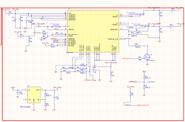
    The chip I used in our product is TMS320C6748EZWTD4.

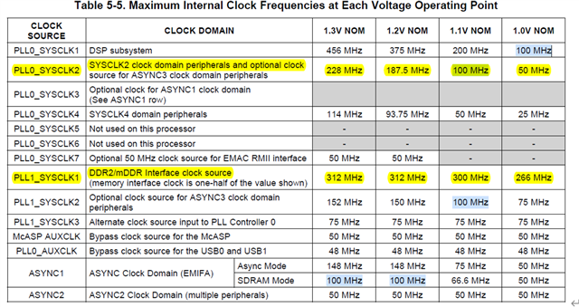
    The CPU freq and DDR freq are both set at 80MHz.

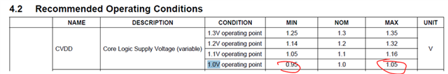
    RVDD is set as 1.2V.

    When CVDD is 1.2V, everything runs OK. Our product can work >10 days stable.

    Now, I want to adjust CVDD to 1.0V to save power.

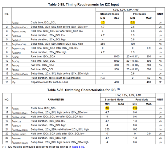
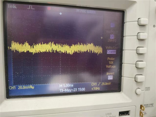
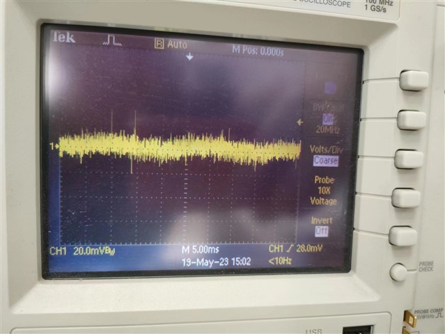
    But when CVDD is 1.0V, the I2C sometime timeout, about several times in 24 hours.

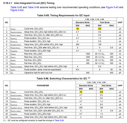
    The I2C is to control BQ25890 and BQ27441, and if there is a I2C timeout, it always happen when read data from BQ27441.

    The test is made with 6 devices, when when CVDD=1.2V, everything goes OK, during 24 hours.

    And when CVDD=1.0V, they will get I2C timeout in 3 hours.

    The CVDD is the only difference. Why?

    Thank you.

Frank

  • Hello Feng Xu,

    Thank you for the query.

    Pls help me understand the power solution you are using. I assume this is a custom board. 

    What is the voltage measured when you set the voltage to 1V while the device is running? 

    Have you had a chance to check the performance with 1.1V?

    Please refer below and confirm the peripherals you are using are supported at the programmed voltage.

    Some interfaces have specific limitations on supported modes/speeds at each operating point. See the corresponding peripheral sections of this document for more information.

    Regards,

    Sreenivasa

  • Hi ,


          I have tried the following changes:      

          1. The CVDD voltage measured is 1.00V, and last night, I also tried 1.06V. The I2C will also timeout when CVDD=1.06V.

          2. The I/O bank of the I2C is 3.30V, and the pullup resistor is 4.7K.(I also tried 2.2K and 10K, nothing changed.)

              In fact, the CVDD should have nothing related with the I2C voltage.

          3. I set down the I2C freq from 400kHz to 100kHz, nothing changed.

              Accroding to the following datasheet, the I2C speed has nothing related with the CVDD.

              I have checked all the peripherals, the I2C/SPI/eMMC, but I think nothing violates the datasheet.

          Regards,

    Frank

  • Hello Feng Xu,

    Thank you for the inputs. 

    The CVDD voltage measured is 1.00V, and last night, I also tried 1.06V. The I2C will also timeout when CVDD=1.06V.

    Not sure on the 1.06V performance, could you please try setting to 1.1V (next OPP) or more for checking. If the issue persists, this could be related to some configuration related to change in OPP.

    Is I2C timeout the only issue you are seeing.

    Pls help me understand the power solution you are using. I assume this is a custom board. 

    Do you have the recommended power supplies on the supply rails.

    Regards,

    Sreenivasa

  • Hi ,

        I will try 1.1V right away.

        Yes, it's a custom board. The power supply is shown below, with BQ650250, which supply 3.3V/1.8V, and now R57/R61/R64 is adjusted to supply 1.2V/1.0V for CVDD. And also the 1.2V LDO output is supplied to the USB and RVDD.

         Regards,

    Frank

  • "Is I2C timeout the only issue you are seeing."

    Besides that, it seems the GPIO sometimes not switch normally, I am not very sure.

  • Hello Feng Xu,

    Thank you.

    I will try 1.1V right away.

    Yes please.

    Also can you please check if the current is changing with the change in the OPP.

    Regards,

    Sreenivasa

  • Hi Kallikuppa Sreenivasa,

        CVDD = 1.1V works normally!!!

        For the power consumption of the whole board, I have made that test before.

       CVDD=1.2V     ---      84.08mA@3.8V

       CVDD=1.0V     ---      74.06mA@3.8V

       I will monitor the current in CVDD=1.1V later.

       As you mentioned, " Not sure on the 1.06V performance, could you please try setting to 1.1V (next OPP) or more for checking. If the issue persists, this could be related to some configuration related to change in OPP. "

       What are the configurations? Is it possible to work at CVDD=1.0V?

       Best regards,

    Frank

  • Hello Feng Xu,

    Thank you.

    CVDD = 1.1V works normally!!!

    Good to hear. Please measure the input current for comparison.

    What are the configurations? Is it possible to work at CVDD=1.0V?

    FYI, please refer my note.

    If the issue persists, this could be related to some configuration related to change in OPP. 

    I do not see any issue here.

    As i mentioned in my early thread.  we need to review if there are any limitations on any of the peripherals when using 1V CVDD.

    I am not familiar with your system and so i would suggest you do a re-review.

    Regards,

    Sreenivasa

  • Hi Kallikuppa Sreenivasa,

         I have done peripherial speed review for the 2nd time, which is shown below. There is no speed violation.   

    Pepriphral Speed Review

    Peripherial

    1.0V Limitation according to datasheet

    Speed in my system

    CPU

    100MHz

    80MHz

    DDR2

    266MHz

    80MHz

    eMMC

    25MHz

    Set by pdk driver, I don’t know the speed. But files are written/read normally.

    SPI0

    Master 25MHz

    4MHz

    SPI1

    Slave  16.67MHz

    1.8MHz

    I2C0

    400kHz

    100kHz

    I2C1

    400kHz

    100kHzcan not work normally

    GPIO

    ---

    ---

    CPU/DDR

    eMMC <=25MHz

    SPI <=25MHz

    Master40ns25MHz

    Slave60ns16.67MHz

    I2C <=400Hz

    JTAG <=15MHz

    1.0V Range

        Is there any other possibilities?

        Regards,

    Frank


  • And I have also tried DSP/DDR speed as 72MHz/72MHz, the issue persists.

  • Hello Feng Xu,

    Thank you.

    Can you measure the supply using an oscilloscope.

    Please make sure you have sufficient caps on the supply rail.

    Regards,

    Sreenivasa

  • Hello Feng Xu,

    Can you confirm the power measurements? 

    For the power consumption of the whole board, I have made that test before.

       CVDD=1.2V     ---      84.08mA@3.8V

       CVDD=1.0V     ---      74.06mA@3.8V

    Regards,

    Sreenivasa

  • Hi Sreenivasa,

        The following is the 1.0/1.8/3.3/1.2V power rail. The 1.2V is for USB. Every rail is good.

        By the way, the DSP is supplied with a 24MHz passive crystal oscillator.

        Thank you.

    Frank

  • Hi Sreenivasa,

        Yes, the above power consumption data is right.

        There is also a BLE/WIFI chip which communicates with DSP via SPI1. During test, the BLE/WIFI chip is only powered and no program runs.

        I have also made a test with BLE/WIFI chip removed, and DSP/DDR set as 36MHz.

        CVDD=1.2V  ---  40mA@3.8V

        CVDD=1.0V  ---  36mA@3.8V

        Regards,

    Frank

  • Hello Feng Xu,

    Please check the ripple on the 1V supply.

    Does the CVDD share the supply with any other devices.

    Regards,

    Sreenivasa

  • Hi Sreenivasa,

       No, CVDD is only supplied to DSP. The following 2 pictures shows CVDD ripple.


       Regards,

    Frank

  • Hi Sreenivasa,

       CVDD=1.2V     ---      84.08mA@3.8V

       CVDD=1.0V     ---      74.06mA@3.8V

       The above data was measured with DSP/DDR freq 100M/120M.

       Today, I use DSP/DDR freq as 80M/80M and do a new measurement. The result is:

       CVDD=1.2V     ---      75.54mA@3.8V

       CVDD=1.1V     ---      67.22mA@3.8V

       CVDD=1.0V     ---      64.68mA@3.8V

       Best Regards,

    Frank

  • Hello Frank, 

    CVDD=1.1V     ---      67.22mA@3.8V

       CVDD=1.0V     ---      64.68mA@3.8V

    I do not see any major difference between 1.1 and 1V. Is this something you can manage?

    Would you be able to reduce the ripple on the supply? 

    Regards,

    Sreenivasa

  • Hi Sreenivasa,

        "Is this something you can manage?" What do you mean?

         I will replace the 10uF Cap with a 22uF, and have a try.

        Thank you.

    Frank

  • Hi Sreenivasa,

         I put 2 more 10uF paralleled with the original10uF Cap, to take 30uF.

        2 boards are tested, the issue persists.

        And I find the problem only occurs when the device is charging and taking SPI communication.

        If the device is not taking SPI communication, the problem does not happen.

        If the device is not charging, the problem does not happen.

        If the CVDD=1.1V, the problem does not happen.

        It's quite strange. 

        I disabled the BQ25890 INT and BQ27441 INT in my program, so when charging, no interrupt is generated. But the issue persists.

        I compared the ripple on 1.0V, when charging and not charging, I think there is no difference.

        Thank you.

    Frank

  • Hello Frank, 

    "Is this something you can manage?" What do you mean?

    I was checking the target current that you were looking at. I dont see a big difference between 1.1V and 1V in terms of current value.

    Regards,

    Sreenivasa

  • Hello Frank, 

    Thank you for the inputs.

    I see difference in the SPI clock rates, have you tried reducing the SPI clock rate?

    Since this seems to be a system level issue, my suggestion is to review all the functions and interfaces and verify if there are any violations.

    With the information i have, i can only provide guidance.

    Regards,

    Sreenivasa

  • Hi Sreenivasa,

         I will have a try to low down the SPI clock rate.

         But my SPI is only 4M and 1.8M, which is far away from the 1.0V limination.

    Peripherial

    1.0V Limitation according to datasheet

    Speed in my system

    SPI0

    Master 25MHz

    4MHz

    SPI1

    Slave  16.67MHz

    1.8MHz

          Regards,

    Frank

  • Hello Frank,

    Please review the below answer

    "Is this something you can manage?" What do you mean?

    I was checking the target current that you were looking at. I dont see a big difference between 1.1V and 1V in terms of current value.

    Regards,

    Sreenivasa

  • Hi Sreenivasa,

          I tried to set SPI0 & SPI1 to 500kHz, and nothing changes.

          And for my last post "Is I2C timeout the only issue you are seeing. Besides that, it seems the GPIO sometimes not switch normally, I am not very sure."           I have remade a test with 4 devices running for 3 days, and checked in every detail. Now, I am sure, the I2C timeout is the only issue. Nothing else abnormal happens.

          And for the power difference between 1.1V and 1.0V. Our product have 2 work modes, with communication and without communication.

          In the 2nd mode(the communication chip is closed), the power is:

             CVDD=1.2V     ---      53.5mA@3.8V

             CVDD=1.1V     ---      48.3mA@3.8V   which is 13.6% more than that in CVDD=1.0V

             CVDD=1.0V     ---      42.5mA@3.8V

          CVDD=1.0V will provide 13.6% more endurance, and down low the temperature. Since our product is a wearable device. So CVDD=1.0V is quite important to us.


         This issue is quite strange, CVDD=1.1V everything is OK, CVDD=1.0V the I2C1 will timeout occasionally.

         The following table shows the SPI and I2C in my system. The I2C0 never timeout.

         And it's strange that, the I2C1 timeout only happens when reading BQ27441.

         And it's strange that, the I2C1 timeout only happens when reading BQ27441, when my device is charing.

         And it's strange that, the I2C1 timeout only happens when reading BQ27441, when my device is charing, and only in the situation that CVDD=1.0V.

         It's really a hard problem. Could you give me some more guidance?

         Thank you.

    Frank

    SPI0

    4MHz

    read sensor data, 500Hz sampling rate

    SPI1

    1.8MHz

    stop in 2nd mode

    I2C0

    100kHz

    read sensor data, 200Hz sampling rate

    I2C1

    100kHz

    read data from BQ25890 & BQ27441, every 15 seconds

  • Hello Frank,

    Thank you for the inputs.

    The early power numbers below was the use case for my question.

    CVDD=1.1V     ---      67.22mA@3.8V

       CVDD=1.0V     ---      64.68mA@3.8V

    Can you set the voltage to 1.07 and do a test. I guess the device should consider the supply as 1.1 OPP and should operate correctly.

    The issue looks to be a system level use case related issue and i am not sure how i could help other than suggesting some test conditions.

    Regards,

    Sreenivasa

  • Hello Frank,

    I see that you clicked the resolved button.

    Can you help me understand if you were able to resolve the issue and add some comments on the finding/resolution.

    Regards,

    Sreenivasa

  • Hi Sreenivasa,

         The problem is very strange. And I have tried 1.06V, which failed with all 4 devices.

         And even if 1.07V works, it cannot guaranteed that all devices works, since there maybe 1%-3% errors between different device power voltages.

         And even 1.07V works with all the devices, the power consumption is near 1.1V. But what we want is 1.0V.

         We think we will move on to other works for our product, and will come back to this issue when we have new ideas.

         Thank you very much for your help and guidance. Please notice me if you have any new guidance.

         Best regards.

    Frank

  • Hello Frank,

    Thank you for the inputs and understand.

    Regards,

    Sreenivasa