This thread has been locked.

If you have a related question, please click the "Ask a related question" button in the top right corner. The newly created question will be automatically linked to this question.

TMS320C6748: Communication between three DSPs using uPP

Part Number: TMS320C6748

Hi experts,

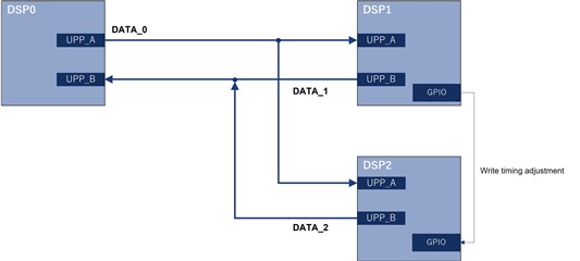
Is it possible to realise the following configuration using the uPP (Universal Parallel Port) of the C6748?

  • Prepare three DSPs and connect them as shown in the diagram below.
  • DSP0 sends the same data to DSP1 and DSP2 simultaneously.
  • DSP0 receives different data from DSP1 and DSP2 at different timings.
    Timing is controlled by the GPIO pins and using labels in the DATA_x to identify DSP1 and DSP2.
Best regards,
O.H

  • What would be your data pin channel assignments? 

    --Paul 

  • Hi Paul,

    Thank you for your reply.

    What would be your data pin channel assignments? 

    We have not yet decided.

    Is it not possible to achieve this depending on the pin to be assigned?

    Best regards,
    O.H

  • The issue I see is that the transmit control/clock signals do not go Hi-z when not transmitting like the data does. You may be able to workaround this by controlling the associated pinmux registers. Note that only channel A pins have this ability. The WAIT signal has no pinmux Hi-z control on either channel. 

    Probably limited to 8-bits + labels

    You will also have to carefully look at the timing and PCB routing if you want to run full speed!

    Be sure that DISP1 and DISPL2 never active at the same time (which you said is controlled by the GPIO). .

    You should prototype this to validate the operation.

    --Paul 

  • Hi Paul,

    Thank you for your reply.

    I understood that if only channel A can set transmit control/clock signals to Hi-Z, which means that channels A and B of DSP1,2 in the following diagram need to be swapped.

    The issue I see is that the transmit control/clock signals do not go Hi-z when not transmitting like the data does. You may be able to workaround this by controlling the associated pinmux registers. Note that only channel A pins have this ability. The WAIT signal has no pinmux Hi-z control on either channel. 

    Why can some pins be Hi-Z by controlling the pinmux register and others cannot?
    I think the pins on channels A and B are assigned GP6 and GP8 functions respectively.

    Be sure that DISP1 and DISPL2 never active at the same time (which you said is controlled by the GPIO). .

    Just to confirm, does this mean that DSP1 and DSP2 must not be active at the same time when receiving?

    Best regards,
    O.H

  • Why can some pins be Hi-Z by controlling the pinmux register and others cannot?

    This is probably a result of the interface being intended for a point to point configuration.

    Just to confirm, does this mean that DSP1 and DSP2 must not be active at the same time when receiving?

    No, just when transmitting so there is no contention. 

    --Paul 

  • Hi Paul,

    Thank you for your reply.

    We plan to discuss the information received with the customer and verify it in a prototype.

    As a result, we believe that the channel limitation and 8-bit limitation can be circumvented by intentionally putting the pins for transmission used by DSP1 and DSP2 into a Hi-Z state using external elements.
    (The external elements are controlled by the GPIOs of DSP1 and DSP2. We think that all data pins (DATA[0:15], XDATA[0:15]) can be used, regardless of channels A and B.)
    Is the above idea realistic?

    No, just when transmitting so there is no contention. 

    I understood.

    Best regards,
    O.H

  • As a result, we believe that the channel limitation and 8-bit limitation can be circumvented by intentionally putting the pins for transmission used by DSP1 and DSP2 into a Hi-Z state using external elements.
    (The external elements are controlled by the GPIOs of DSP1 and DSP2. We think that all data pins (DATA[0:15], XDATA[0:15]) can be used, regardless of channels A and B.)
    Is the above idea realistic?

    Yes, just be careful of any impact to timing. 

    Another possible option  would be to use external logic to AND/OR the signals as appropriate, that way you don't have to worry about floating signals. Again, remember to check for impacts to timing. 

    --Paul 

  • Hi Paul,

    Thank you for your support.

    Yes, just be careful of any impact to timing. 

    Another possible option  would be to use external logic to AND/OR the signals as appropriate, that way you don't have to worry about floating signals. Again, remember to check for impacts to timing. 

    We will proceed with customer based on the information you give us.

    If additional questions arise, we will create a new thread.

    Bets regards,
    O.H