This thread has been locked.

If you have a related question, please click the "Ask a related question" button in the top right corner. The newly created question will be automatically linked to this question.

DRA821U: Accessing multiple serial UARTs on QNX

Part Number: DRA821U
Other Parts Discussed in Thread: DRA821

Hi,

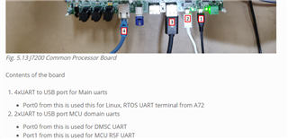
We are hoping to have more than 1 UART port usable for serial comms at once running QNX. Our intended result is to have 3 main ways of communicating with the processor; Ethernet (working), a primary serial connection (Main_UART0 presumably, the default) and a backup serial port for redundancy. 

As it stands, it looks like all the other UART ports are disabled by default, and I can't seem to start up the drivers to access them. I was looking at the SDK and did find 'k3-j7200-common-proc-board.dts' which lists all the UART port statuses as 'disabled'. Do I need to change these and recompile this part of the SDK? I'm not sure what gets compiled here, as I've so far only really compiled the QNX BSP. 

Additionally, is it possible for the second UART port to connect to MCU_UART rather than MAIN_UART[1-9]? Would there be an advantage to us to do it this way? 

I have tried running the drivers and tinit in QNX to get them running, but without success:

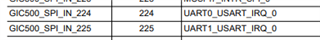
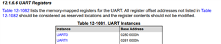
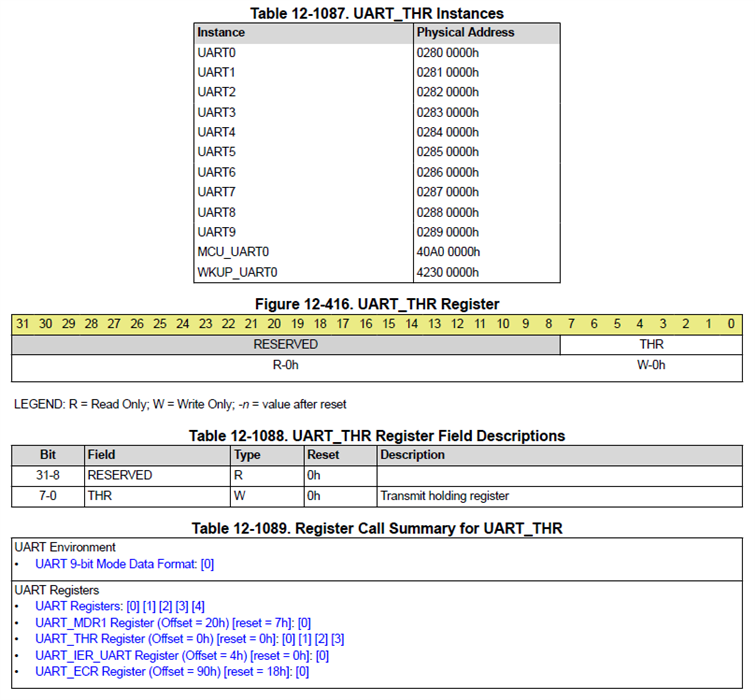
# devc-seromap -e -F -b115200 0x02810000,224
#
# tinit -f /sd/ttys.txt

Where ttys.txt looks like:

`/dev/ser2 "/bin/login" qansi-m on`

Thanks for any help!

Michael. 

  • Hi Michael,

    In general there is no reason you cannot have multiple serial ports running on QNX.   Will provide some high level thoughts on things to check:

    1. Pin Muxing - The input pins for the UART port being enable must be set correctly.   Where they are being set will depend on your boot flow.   
      1. Reference your schematics, identify the pins for working UART, and additional UART to be enabled
      2. Reference the device datasheet to identify pin naming:  https://www.ti.com/lit/gpn/dra821u .
      3. Reference TRM for addresses of pin mux configuration registers https://www.ti.com/lit/pdf/spruiu1 
      4. Once you know the addresses for the working / non-working UARTs, dump them from QNX command prompt, using 'k3conf read <address>" or attach a debugger to see register values
        1. If working UART pin muxes, are equal to non-work UART pin mux values all good
        2. If working UART pin mux registers are not equal to non-working UART registers, the non-working may need to be updated.  For a quick test they can be modified by "k3conf write <address>" and the serial driver restarted to see if it makes a difference.
    2. Ensure Base Address and Interrupt for desired UART module are correct
      1. Looking at the command line which was used "# devc-seromap -e -F -b115200 0x02810000,224". 
      2. Looking at TRM, the command line is not correct.  IRQ 224, is for UART0.  Based Address 0x0281_0000 is for UART1
      3. If UART1 module is desired UART, IRQ should be 225.

    3. The DRA821 has multiple cores.   Ensure that the "new" UART is not being used by the R5 core.  There can only be one controller of a given UART instance.

    4. Increase verbosity of driver when launching, likely there is a -v option, see "use devc-seromap" for usage.  Then check logs "slog2info" for errors,

    5. At this point expectation is that everything is fine from a H/W perspective.   Check with QNX/Blackberry team for best approaches in supporting two UART instances running in parallel on A72.

    Regards,

    kb

  • Hi KB,

    I was able to stop the serial driver, and then I could see the UART0 with `k3conf read 0x2800000` returns 0x0000000d. If I try to write this to UART1 with `k3conf write 0x2810000 0x0000000d` it just reports back it is still equal to 0x0. Do I need to make a change in the BSP to be able to update this value? 

    I am able to shutdown the UART0 connection and bring it back online again, using telnet to access the unit. 

    Thanks for the error on the IRQ, I'll fix that going forwards. 

    Cheers,

    Michael. 

  • Hi Michael,

    TRM https://www.ti.com/lit/pdf/spruiu1, shows that bitfield as Write only.

    Has verbosity been increased for UART1 driver, and logs checked?

    devc-seromap -v -e -F -b115200 0x02810000,225

    Regards,

    kb

    J7EVM@QNX:/# devc-seromap -v -e -F 0x02810000,225
    J7EVM@QNX:/# slog2info
    Jan 01 00:01:37.405            devc_seromap.192532                 slog*     0  Port ...................... /dev/ser2 (0x2810000)
    Jan 01 00:01:37.405            devc_seromap.192532                 slog      0  IRQ ....................... 0xe1
    Jan 01 00:01:37.405            devc_seromap.192532                 slog      0  Rx fifo trigger ........... 16
    Jan 01 00:01:37.405            devc_seromap.192532                 slog      0  Tx fifo trigger ........... 8
    Jan 01 00:01:37.405            devc_seromap.192532                 slog      0  Rx flow control highwater . 1920
    Jan 01 00:01:37.405            devc_seromap.192532                 slog      0  Input buffer size ......... 2048
    Jan 01 00:01:37.405            devc_seromap.192532                 slog      0  Output buffer size ........ 2048
    Jan 01 00:01:37.405            devc_seromap.192532                 slog      0  Canonical buffer size ..... 256
    
    
    J7EVM@QNX:/# use devc-seromap
    devc-seromap - Serial driver for TI OMAP
    
    devc-seromap [options] [port[^shift][,irq][,k]] &
    Options:
     -a           Use auto-rts when hardware flow control is enabled
     -b number    Define initial baud rate (default 115200)
     -c clk[/div] Set the input clock rate and divisor
     -C number    Size of canonical input buffer (default 256)
     -e           Set options to "edit" mode
     -E           Set options to "raw" mode (default)
     -I number    Size of raw input buffer (default 2048)
     -f           Enable hardware flow control (default)
     -F           Disable hardware flow control
     -M           Disable MSR interrupt
     -O number    Size of output buffer (default 2048)
     -s           Enable software flow control
     -S           Disable software flow control (default)
     -t number    Set receive FIFO trigger level (default 16)
     -T number    Set transmit FIFO trigger level (default 8)
     -u unit      Set serial unit number (default 1)
     -l (0|1)     Enable Loopback mode (1=on, 0=off)
     -v           Set verbosity level
    

  • Hi kb,

    The output with verbosity increased is below:

    # devc-seromap -v -e -F 0x02810000,225
    # Jan 01 00:21:17.937            devc_seromap.237582                           0  -----ONLINE-----
    Jan 01 00:21:17.937            devc_seromap.237582                 slog*     0  Port ...................... /dev/ser1 (0x2810000)
    Jan 01 00:21:17.937            devc_seromap.237582                 slog      0  IRQ ....................... 0xe1
    Jan 01 00:21:17.937            devc_seromap.237582                 slog      0  Rx fifo trigger ........... 16
    Jan 01 00:21:17.937            devc_seromap.237582                 slog      0  Tx fifo trigger ........... 8
    Jan 01 00:21:17.937            devc_seromap.237582                 slog      0  Rx flow control highwater . 1920
    Jan 01 00:21:17.937            devc_seromap.237582                 slog      0  Input buffer size ......... 2048
    Jan 01 00:21:17.937            devc_seromap.237582                 slog      0  Output buffer size ........ 2048
    Jan 01 00:21:17.937            devc_seromap.237582                 slog      0  Canonical buffer size ..... 256
    
    
    #
    # devc-seromap -v -e -F 0x02800000,224
    # Jan 01 00:21:35.280            devc_seromap.241690                           0  -----ONLINE-----
    Jan 01 00:21:35.280            devc_seromap.241690                 slog*     0  Port ...................... /dev/ser2 (0x2800000)
    Jan 01 00:21:35.280            devc_seromap.241690                 slog      0  IRQ ....................... 0xe0
    Jan 01 00:21:35.280            devc_seromap.241690                 slog      0  Rx fifo trigger ........... 16
    Jan 01 00:21:35.280            devc_seromap.241690                 slog      0  Tx fifo trigger ........... 8
    Jan 01 00:21:35.280            devc_seromap.241690                 slog      0  Rx flow control highwater . 1920
    Jan 01 00:21:35.280            devc_seromap.241690                 slog      0  Input buffer size ......... 2048
    Jan 01 00:21:35.280            devc_seromap.241690                 slog      0  Output buffer size ........ 2048
    Jan 01 00:21:35.280            devc_seromap.241690                 slog      0  Canonical buffer size ..... 256

    This is running with the development kit, if that makes a difference? I am hoping to see the login prompt appear on one of the other COM ports on my computer, given there are 4 shown in my device manager. There are an additional 2 COM ports from the MCU UART port, which also seem to be inactive.

    Thanks,

    Michael.

  • Hi Michael,

    Regarding "This is running with the development kit",  can you please provide some details on the development kit that is being used.  Is the J7200XSOMXEVM Evaluation board | TI.com, being used?

    Thanks,

    kb

  • Hi kb,

    Yes, that is the board we are using for now.

    Cheers,

    Michael. 

  • Hi Michael,

    The J7200 EVM UART ports are listed at 5. EVM Setup for J7200 — Processor SDK RTOS J7200 (ti.com).  The TI SDKs UART drivers are configured accordingly.

    Regards,

    kb

  • Hi KB,

    Does this mean we cannot get a second serial connection to the unit with the evaluation board? Or that the SDK is not configured for it?

    Thanks,

    Michael.