This thread has been locked.

If you have a related question, please click the "Ask a related question" button in the top right corner. The newly created question will be automatically linked to this question.

TDA4VE-Q1: [P2 ADC][TDA4VE] I2C Clock Frequency issue

Part Number: TDA4VE-Q1

Hi. TI

Project name: P2 ADC

SDK version: 8.05

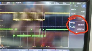
We are doing the ECU A sample bring up. We face a issue with the I2C rate. The I2C rate is only 320K when we config the I2C with 400K?  It is very urgent for us to it. Could you help analyze the issue. Thanks!

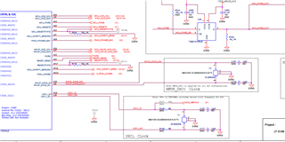
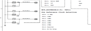
The code runs fine in EVM VL board before. Now the ECU change to use the VE SOM, I want to know does there any PLL or Frequency We need to change? 

  • Hi Biao,

    Which i2c instance are you using? Also how do you measure that i2c frequency to be 320Kb? Could you please provide some more information on this? 

    Regards,

    Brijesh

  • Hi. Brijesh

    We use I2C instance 4. Frequency of 320Kb is measure with the oscilloscope.

    We found a changes for external crystal oscillator. The EVM board using 19.2Mhz. Our ECU changes to 25Mhz.

    Does the pdk need to change?

  • Hi, Please check the waveform.

  • Hi biao song,

    Can you please check and confirm that boot pins (MCU_BOOTMODE[2:0]) are setup correctly to indicate 25MHz sysclock?

    Regards,

    Brijesh

  • Hi. Brijesh

    Yes. It is set to 25Mhz.

  • Hi. Brijesh

    The issue occur on I2C_4. BTW, We also checked the I2C_6 on our ECU board. The I2C_6 rate is almost 380Kb. 

  • Hi Biao Song,

    What i am suspecting is the PLL setup is incorrect. Can we please read PLL registers and share them? Can you also readback I2C internal divisor registers to see if it is configured correctly? Can you please share the values at below register offset?

    0x00681030

    0x00681038

    0x00681080

    0x00681084

    0x020400B0

    0x020400B4

    0x020400B8

    Regards,

    Brijesh

  • Hi, Brijesh

    Please check the values.

    0x00681030 ---0x0000004c

    0x00681038 ---0x01020001

    0x00681080 ---0x00008009

    0x00681084 ---0x00008005

    0x020400b0 ---0x00000007

    0x020400b4 ---0x00000008

    0x020400b8 ---0x0000000a

  • Hi Biao,

    Can you please share the value at 0x00681034 also?

    Regards,

    Brijesh

  • Hi, Brijesh

    Please check. Thanks!

    0x00681034 ---0x00cccccd

  • Hi. Brijesh

    Please let me know if you have any findings. Thanks!

  • Hi Biao,

    The clock seems to be matching with what is configured on EVM. It is configured to output 96MHz, same as EVM.

    But i am suspecting something else. Can we please replace SCLL and SCLH registers with different value and see if you are able to get 400KHz correct frequency? Can you please try setting value at 0x020400b4 offset to 7 and value at 0x020400b8 offset to 5 and see if it helps? 

    Regards,

    Brijesh

  • Hi, Brijesh

    Thank for your suggestion. The Clock of I2C instance 4 can achieve 400k. 

    But the I2C communication issue still exist. 

    ECU: TDA4VE

    Deser: UB9702

    Ser: UB935

    Imager sensor: OVT X3A

    At first we found the I2C_4 communication failed issue with UB935. It can communicate with UB9702, But it is failed when it communicate UB935 through FPD link. So we check the CLK using oscilloscope and it is only 330K. So we suspend the issue is the CLK is not accurate.  

    Do you have any ideal?

    The below picture is communication with UB9702:

    The below picture is communication with UB935

  • Hi Biao,

    Do you mean the i2c clock between sensor and ub935 is failing? Is it failing for specific register or failing for all registers? Also can you please confirm if sensor is powered on or anything required on the board to power it on?  I really doubt that this failure is related to i2c speed between deserializer and TDA4. 

    Regards,

    Brijesh

  • Hi. Brijesh

    Yes. Exactly. It is failing for all registers. The SW stuck in ReadReg or WriteReg. Btw we use the I2C6 to write register and it works fine. I don't know why there is difference.

  • Hi Biao,

    did not get it. Which i2c instance is connected to this deserializer? Is it i2c4 or i2c6? I don't think there is any difference between i2c4 and i2c6. If it is working for i2c6, from the module perspective, there is no reason why it should not work for i2c4. 

    Regards,

    Brijesh

  • Hi. Brijesh

    The I2C4 is connected to the deserializer. 

  • Hi biao,

    ok, as i understand, i2c6 is as such able to communicate at 400khz, but i2c4 is not able to communicate with the sensor. 

    Are you able to read serializer register? Can you please read some registers of ub935 and see if it is accessible? Most likely if SERDES are locked, it should be accessible. 

    Also once ub935 is accessible, please try to read some status register to confirm if ub935 is able to detect sensor.. 

    Can you also check and confirm sensor is powered on or anything required to power on the sensor? 

    Regards,

    Brijesh

  • Hi. Brijesh

    The serializer register is not accessible over I2C4. The sensor should be powered. Because it works fine when switching to the I2C6. 

    I have take some waveform. Using I2C4 and I2C6 to read register after connecting I2C4 with I2C6 over Hardware. 

    The I2C4 can't pull it up and It seems deadlocked.

    I2C6 read register:

    I2C4 read register:

  • Hi. Brijesh

    Please refer to the register dumping from CCS.  Thanks!

    I2C Register(I2C6&I2C4).zip

  • Hi Biao,

    I dont think there is any issue in the I2C, since you are able to access deserializer and configure it. We even confirmed with the above changes the I2C is working at 400khz, even if it is running slower, it can still communicate with remote device, if remote device is accessible. 

    So i think the issue might be something on the camera board. 

    I am still confused on i2c6 usage. Are you able to access serializer using i2c6, but not with i2c4? Are both of these instances connected to deserializer to access serializer? If not, how are you able to access serializer using i2c6?

    Regards,

    Brijesh

  • Hi. Brijesh

    Let's make it more clear. 

    Let me introduce the background:

    TDA4VE ECU board:

    I2C4 is connect to UB9702 for video input and UB9702 use FPD link with camera(UB935+X3A). I2C6 connect to Max9295 for Video output and Max9295 use FPD link with Duxin device(Max9296A).

    We do three case test for the issue:

    case 1: The connection between the hardware I2C4 and I2C6 is not changed.

    Just use I2C4 to communicate for video input. It can communicate with UB9702 but it can not communicate with both UB935 and X3A.

    Just use I2C6 to communicate for video output. It can communicate with Max9295.

    case2: Change the hardware to connect the I2C4 and I2C6.

    Use I2C6 to communicate for video input. It can communicate with both UB9702 and UB935 and X3A.

    case 3: Change the hardware to connect the I2C4 and I2C6.

    Use I2C4 to communicate for video output. It can't communicate with Max9295.

  • Hi biao,

    ok understood. 

    Can you please check below two things?

    #1, Please check if i2c4 is disabled from Linux. If you are accessing i2c4 from R5F, it must be disabled in the Linux dts file. In vision apps dtb file, it is explicitly disabled by below node. So can you please check if this is disabled in your environment also?

    &main_i2c4 {
    status = "disabled";
    };

    #2, Looking at the pinmux document, i see i2c4 output is possible on 3 output pins. Can you please check if it is enabled only on the pins which you have connected to the serializer/deserializer and for the other pins, i2c4 functionality is not enabled?

    Regards,

    Brijesh  

  • Dear Brijesh

    #1. I2C4 has been disabled in the device tree.
    #2. The configured pins are also the pins drawn on the schematic diagram, confirm that they are only used on the serializer/deserializer.

    Regards,

    Liu

  • Hi Liu,

    When this issue occurs, can you please read below registers and share their values?

    0x0011C010

    0x0011C014

    0x0011C080

    0x0011C084

    0x0011C0F8

    0x0011C0FC

    Regards,

    Brijesh

  • Dear Brijesh

    Please check the values.


    When using i2c6:

    0x0011C010, value: 00050008
    0x0011C014, value: 00050008
    0x0011C080, value: 00010007
    0x0011C084, value: 00010007
    0x0011C0F8, value: 0005000a
    0x0011C0FC, value: 0005000a

    When using i2c4:

    0011c010, value: 00050008
    0011c014, value: 00050008
    0011c080, value: 00010007
    0011c084, value: 00010007
    0011c0f8, value: 0005000a
    0011c0fc, value: 0005000a

    Regards,

    Liu

  • Hi Liu,

    On which pads, have connected your serializer/deserializer on i2c4? Are you using (AF28 and AD25) or (M23 and P24) balls for I2C4? 

    I see both of below pinmux register are set for i2c4 output.. Can you please select i2c4 functionality only for pins that you are using? For the other pin, can you please change the pins to GPIO or other functionality?  

    0011c010, value: 00050008
    0011c014, value: 00050008

    0011c0f8, value: 0005000a
    0011c0fc, value: 0005000a

    Regards,

    Brijesh

  • Dear Brijesh

    Indeed, according to the information you provided, modify the pin mode of AF28 and AD25 from i2c4 to MCAN: configure both 0x0011C010 and 0x0011C014 to 0x00050000, and i2c4 can work normally.

    Please tell me, taking AF28 as an example, I saw from the code that the pinmax configuration is actually 0x4301C010, why do you need to configure the register 0x0011C010?

    Regards,

    Liu

  • Hi Liu,

    Mode8 (ie value 00050008) in 0x0011c010 and 0x0011c014 registers is actually used for i2c4. So if you have i2c enabled on multiple pins, it may not work.. This is not recommended. Please enable the i2c only on the pins where it is connected to the slave device.. 

    Regards,

    Brijesh

  • Dear Brijesh

    Maybe I didn't say it clearly enough, please see the screenshot. What I mean is that the address seen in the register manual is 0x4301C010, why do you need to configure 0x0011C010 to take effect instead of configuring 0x4301C010?

    Regards,

    Liu

  • Hi Liu,

    Please use the register offset that i gave you ie 0x0011C010 and 0x0011C014. Location 0x4301C010 given in the datasheet seems also correct, but that may have to be used differently. 

    Regards,

    Brijesh

  • Dear Brijesh

    We checked the code corresponding to configuring pinmax and the VM manual and found:
    1.0x0011C000 corresponds to the pinmax base address of the MAIN domain
    2.0x4301C000 corresponds to the pinmax base address of the WKUP domain

    The current I2C4 problem is caused by the pinmax configuration of AF28 and AD25 being multiplexed to I2C4. We modify the pin mode of AF28 and AD25 from i2c4 to MCAN, and the repair and verification is OK. Thank you for your support.

    Regards,

    Liu

  • Thanks Liu, there are no further open questions, so closing this ticket.