- Ask a related questionWhat is a related question?A related question is a question created from another question. When the related question is created, it will be automatically linked to the original question.
This thread has been locked.
If you have a related question, please click the "Ask a related question" button in the top right corner. The newly created question will be automatically linked to this question.
Hi Expert!
We are using AM625 based our custom HW.
We created images using yocto with TI-META and flashed into RAM using usb dfu tool.
We are able to load RAM till u-boot and got console then we loaded our eMMC image using usb dfu-util tool.
Once we load all bootloader then rootfs and gave below command on u-boot console.
U-Boot# bootm 0x82000000
then board booted properly with above command.
After that we did below steps.
After completing above steps we are not able to see the boot logs with single line also.
We thought B22 pin is already input so we marked as output and generated bins, so tested but logs are not coming.
see the below pic for our schematic connection.

We changed k3-am62x-sk-common.dtsi as mention in below.
main_mmc1_pins_default: main-mmc1-pins-default {
pinctrl-single,pins = <
AM62X_IOPAD(0x23c, PIN_INPUT, 0) /* (A21) MMC1_CMD */
AM62X_IOPAD(0x234, PIN_OUTPUT, 7) /* (B22) MMC1_CLK */
Anything we need to change extra ? to get logs for eMMC boot.
Please help us!
Thanks,
Suraj.
Hello Suraj.
Thank you for the query.
Can you help me confirm if the eMMC reset is being asserted by the GPIO or do you have an anding logic similar to the EVM.
I need more information including the schematics of the eMMC interface including reset if you want me to review.
Alternatively please follow the EVM implementation.
You will have to connect the resetstatz to the eMMC reset to be able to boot.
Regards,
Sreenivasa
Hi Sreenivasa,
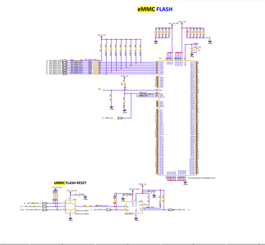
Please find the below eMMC reset schem.

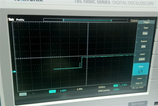
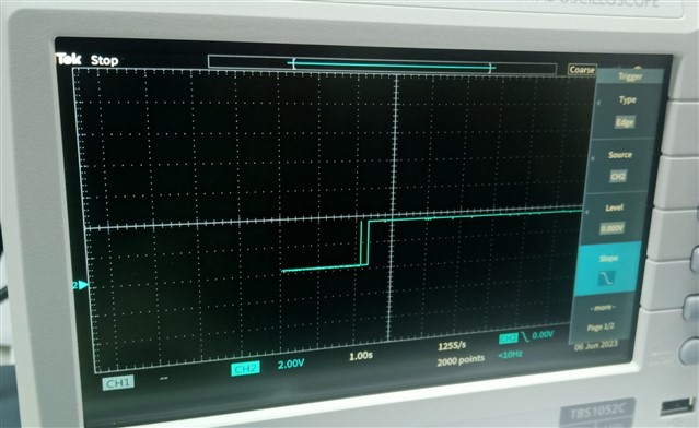
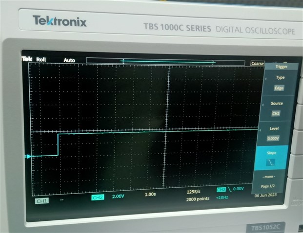
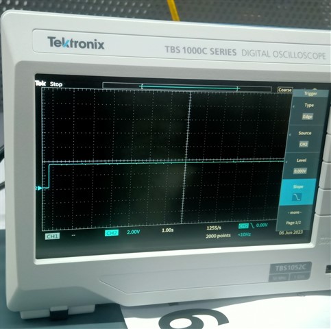
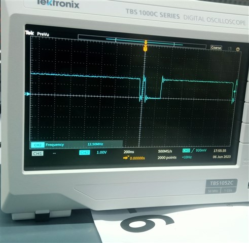
We made GPIO signal high and U14 (Pin-3 &6) are high, also we monitored eMMC_RSTn signal which is high.
Please find attached images for reset signal. And CMD signal of the eMMC flash while the switch setting for eMMC flash boot.
Provided images with there respective name for signal and schematic.
Kindly let me know any other info required.

Thanks,
Suraj
Hello Suraj,
For the anding logic, i am not sure if pulling all the inputs high is a recommended approach. I would expect only the GPIO input to have a pullup.
Please review the EVM schematics that you are referring and optimize the pulls used for the anding logic and the level shifter.
We wont be able to review the schematics shared as picture. I will need a PDF in case you want me to do a quick review.
Regards,
Sreenivasa