This thread has been locked.

If you have a related question, please click the "Ask a related question" button in the top right corner. The newly created question will be automatically linked to this question.

TMS320C6678: DDR3 bit error involving clock generator and AC coupling

Part Number: TMS320C6678

We have recently begun having irregular, but recurring DSP DDR3 issues with a board designed several years ago. Upon startup self-test, the affected boards are reporting a DSP DDR3 bit error — a rather generic pass/fail message, unfortunately. While we are still digging into exactly what is causing this error to be generated, it was noticed that if either of the 0.1µF AC coupling capacitors on the DDRCLKP and DDRCLKN inputs of the DSP are momentarily probed with a standard 8pF, 500MHz oscilloscope probe, the affected boards will pass self-test and continue to operate normally — even after the probe is removed.

 I have been trying to run the root cause of the problem down, but I have no previous experience with this design and the issue appears to be a subtle one since it does not affect all boards. Boards have failed both in the field and right off the production line. The components involved are:

  • DSP - Texas Instruments TMS320C6678ACYPA
  • DDR3 - Micron MT41K256M16HA-125AAT
  • Clock generator - Texas Instruments CDCM6208V1RGZT
  • DDRCLK AC coupling capacitors - 0.1µF, CHIP, 0402, X7R, 0.1UF, 10%, 16V 

Replacement of one or more of these components will sometimes resolve the issue, but not always. I have looked at the supply filtering circuit for AVDDA2 on the DSP, but it follows the design recommendations and I see no obvious issues. Assistance would be appreciated!

  • Hello Robert,

    Can you give more details on the fail?  E.g., is it one or more bits that are failing?  What is the fail rate?   Can you run a focused "memtester" type test to be able to report lower level details?

    Thanks,

    Kyle

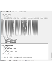
  • On the boards with the failure, all of the bits are failing (walking ones, zeros). This is typical output from the basic RAM self-test in the bootloader:

    Loading new test code into production boards to do more detailed troubleshooting is problematic since the flashing process requires access to the SDRAM. Since that's what's failing, there'd be a significant risk of bricking the boards since we don't understand the why or trust the probing of the capacitors to keep the system stable long enough to complete a reflash.

  • Hi Robert,

    to do more detailed troubleshooting is problematic since the flashing process requires access to the SDRAM. Since that's what's failing, there'd be a significant risk of bricking the boards

    It sounds like the flashing procedure is relying on existing production test code already stored in a non-volatile memory on the board. At some point though, that memory did not have any code. How does the production code get loaded on a brand new board?

    Separate from modifying the production code, do you have JTAG access which would allow you to run bare-metal tests / poke memory if needed?  

    Have you tried performing a register dump of the DDR registers comparing a bad and good system?

    Have you monitored voltage rails, including CVDD, to ensure they match expected values?

    Regards,
    Kevin

  • Hello Robert,

    To add to Kevin's questions ... from the uboot walking 1s test ... this is a gross fail.  Can you try to reflow/resolder the board to see if there are problems with the PCB?

    Thanks,

    Kyle

    • The flash is preprogrammed prior to being placed on the boards.
    • We have access to the emulator via JTAG; I'm not sure if this answers your question.
    • I'm told a full register dump hasn't been captured, just portions grabbed piecemeal. That is something that probably got derailed when probing the DDRCLK AC coupling caps yielded results and the issue was handed off to hardware to troubleshoot.
    • The voltage rails are matching expected values.
  • We've tried that. Sometimes it works, and sometimes it doesn't. All rework has been done by trained operations personnel qualified to carry it out and not just by a lab technician, and I have little reason to doubt their competence. Unfortunately, we don't have the luxury of scrapping every failed board to section it and look for photoresist masking failures, FOD, cracked or badly plated vias, etc., or perform dye penetration and pull the parts off the board to check the BGA solder joints. Right now I have exactly one board I have the option to perform destructive testing upon, and that will only be as a last resort.

  • We've finally been able to track down the DSP emulator, set it up on a lab computer, and confirmed we can talk to the boards. We now just need to write some test code to dump the contents of the DDR registers.