This thread has been locked.

If you have a related question, please click the "Ask a related question" button in the top right corner. The newly created question will be automatically linked to this question.

AM623: Hyperlynx - RMII Simulation result is confusing

Part Number: AM623
Other Parts Discussed in Thread: SK-AM62-LP

Hi TI team,

I made a hyperlynx simulation for the RMII interface between the AM623 (IBIS file sprm766c.ibs) and an ethernet PHY DP83825 (sprm766c.ibs) with the following schematics`(both with 1.8V levels):

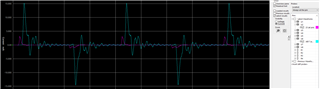
The simulation results show the following: CPU is the driver (pink) / PHY is the driver (blue)

to look a the currents, you can see that the PHY can drive much more when switching, than the CPU:

Could this be real? Has the CPU really such - sorry for the wording - poor drivers, or is there a failure in the IBIS model?

  • Hello Raik Melzer,

    Thank you for the query.

    I am checking internally with the simulation team.

    Could you share the buffer configuration that you are using.

    The DP83825 has internal series resistors - Did you configure it to 25R or 50R.

    Can you add a similar resistor at the SoC output and do a check.

    Regards,

    Sreenivasa

  • Hi Sreenivasa,

    the model of the DP83825 I can only select 1.8 or 3.3 V driver - not the output series resistor...
    In the datasheet, there is also no resistor selection possible...

    When I run the termination wizard in hyperlynx (CPU is the driver), the following information will be shown

      the automatic optimized terminiation is 0 Ohms in series, because the driver impedance is very high (58 ohms).

    When I add a series resistor in range of 25 ohms or higher, the waveforms get kind of monotonic, but with quiet bad slew rates:

    (orange is without series resistor / pink with 50 ohms) - but this is just a 50 MHz RMII clock...

    It seems, that the driver is not able to drive the capacitive load of the line - using a series resistor is just to limit the current and not overrun the output driver. 

    Using RGMII the clock is 125MHz and the scope looks like the following:

    pink is with 0 Ohm in series / green with 25 Ohms. I would not say, that one of both signals is as it should be...

    Here's the buffer setting for the CPU outputs:

  • Hello Raik Melzer,

    I am reviewing the inputs.

    Please refer below.

    In the datasheet, there is also no resistor selection possible...

    Regards,

    Sreenivasa

  • Ok, found it also in datasheet...but not in IBIS model.

    But the issue is the AM623, not the PHY...

  • Hello Raik Melzer,

    Thank you.

    Do you see any change in the waveform when you connect the TX of the SoC to the RX of the SoC and RX  of EPHY to the TX of the EPHY.

    I am reviewing the inputs you provided and will have to check internally with the simulation experts.

    regards,

    Sreenivasa

  • Hi Sreenivasa,

    this change seems not to make a huge difference...

      (length difference in linesim (10 vs 6 cm) is not the issue)

    still no monotonic waveform for AM623....PHY is good.

    Pincurrent is also worse for AM623

  • Hello Raik Melzer,

    Thank you.

    Could you please help me confirm if the RMII signals/RGMII signals have any other buffer configuration that can be selected.

    Regards,

    Sreenivasa

  • Hi Sreenivasa,

    in the IBIS model file only one model type is defined for RMII/RGMII Arrow right LVCMOS_V

    AB17 RGMII1_RD0 LVCMOS_V
    AC17 RGMII1_RD1 LVCMOS_V
    AB16 RGMII1_RD2 LVCMOS_V
    AA15 RGMII1_RD3 LVCMOS_V
    AE17 RGMII1_RX_CTL LVCMOS_V
    AD17 RGMII1_RXC LVCMOS_V
    AE20 RGMII1_TD0 LVCMOS_V
    AD20 RGMII1_TD1 LVCMOS_V
    AE18 RGMII1_TD2 LVCMOS_V
    AD18 RGMII1_TD3 LVCMOS_V
    AD19 RGMII1_TX_CTL LVCMOS_V
    AE19 RGMII1_TXC LVCMOS_V
    AE23 RGMII2_RD0 LVCMOS_V
    AB20 RGMII2_RD1 LVCMOS_V
    AC21 RGMII2_RD2 LVCMOS_V
    AE22 RGMII2_RD3 LVCMOS_V
    AD22 RGMII2_RX_CTL LVCMOS_V
    AD23 RGMII2_RXC LVCMOS_V
    Y18 RGMII2_TD0 LVCMOS_V
    AA18 RGMII2_TD1 LVCMOS_V
    AD21 RGMII2_TD2 LVCMOS_V
    AC20 RGMII2_TD3 LVCMOS_V
    AA19 RGMII2_TX_CTL LVCMOS_V
    AE21 RGMII2_TXC LVCMOS_V

    And in the model selector of LVCMOS_V, only two buffer types can be selected - 1.8V and 3.3V:

    [Model Selector] LVCMOS_V
    lvcmos0_nom_1p8_v PRWDWUWSWEWCDGLVCMOS_V@_Nom_1p8_comment
    lvcmos0_nom_3p3_v PRWDWUWSWEWCDGLVCMOS_V@_Nom_3p3_comment


    Also the MMCx signals have only the models SDIO_H and SDIO_V and those can also be only chosen for 1.8 and 3.3V

    [Model Selector] SDIO_V
    |****************** SDIO
    [Model Selector] SDIO_H
    sdio1_r40_1p8_h PRWDWUWSWEWCDGSDIO_H@_R40_1p8_comment
    sdio1_r40_3p3_h PRWDWUWSWEWCDGSDIO_H@_R40_3p3_comment
    |
    |
    [Model Selector] SDIO_V
    sdio0_r40_1p8_v PRWDWUWSWEWCDGSDIO_V@_R40_1p8_comment
    sdio0_r40_3p3_v PRWDWUWSWEWCDGSDIO_V@_R40_3p3_comment

    But for driving a 200 MHz signal (eMMC HS200 mode), this are also very less options... (maybe I should open an additional ticket with the poor eMMC simulation results?)

    Regards,
    Raik

  • Hello Raik Melzer,

    Thank you for the inputs.

    Did you have a chance to check the 3.3V output buffer behavior for the RMII or RGMII?

    regards,

    Sreenivasa

  • not a huge difference except voltage level...

  • Hello Raik Melzer,,

    Thank you.

    Let me check internally with the simulation expert.

    I will update you with his thoughts or suggestions.

    Regards,

    Sreenivasa

  • Hello Raik Melzer,,

    Quick Update: The simulation expert is on vacation and expected to be back next week.

    I will follow-up and update you with the inputs i receive.

    Regards.

    Sreenivasa

  • Hello Raik Melzer,

    Thank you for waiting.

    Below are the inputs that i received from the experts. 

    The middle element looks like a board (since there is some STACKUP specified) but might be worth double-checking.

    Also, the impedance of this element appears to be 51.6 ohms which is clearly mismatched with a 40-ohm buffer. I do not understand why they are surprised at their results.

    The non-monotonic event is being caused by an impedance mismatch in the output buffer and the PCB trace.  I suspect they could increase the value of the 0 ohm series resistor to reduce the secondary reflection that is causing the non-monotonic event.  However, this non-monotonic event does not appear to be significant since it is outside of the input buffer switching.

    Yes, the non-monotonicity in the waveforms is small and should not impact buffer operation.

    Regards,

    Sreenivasa

  • Hello Sreenivasa,

    now I'm wondering a little bit...where have I told anything about a 40 Ohms driver?

    If there would be a 40 Ohms driver, all would be fine, because I can use a series resistor.

    When you look on my first comment above, you'll see, that the driver impedance is 58.1 Ohms (screenshot from termination wizard). The driver impedance is too high and cannot drive the signal as fast as needed.

    In the mean time I've made some real measurements with the SK-AM62-LP development board. On the 3.3V RGMII signals, the measurements are way better than the simulation results. So I still think, that the IBIS model of the AM623 is the issue...

    Regards,
    Raik

  • Hello Raik Melzer,

    Thank you for the inputs and good to know you have been able to make measurements.

    now I'm wondering a little bit...where have I told anything about a 40 Ohms driver?

    The 40 Ohm driver impedance information was provided by the simulation expert. I guess this is the expected SoC driver output impedance.

    So I still think, that the IBIS model of the AM623 is the issue...

    I will provide the inputs to the simulation expert to verify.

    Regards,

    Sreenivasa

  • Hi Sreenivasa,

    yes - please double check with the experts - I can not confirm that the impedance is 40 ohms.
    If the drivers had a lower value, a series resistor would have solved the problem - but this is not the case.

    Regards,
    Raik

  • Hello Raik Melzer,

    Thank you. 

    Let me check internall.

    I can not confirm that the impedance is 40 ohms.

    Pls help me understand what did you mean by can not ?

    Regards,

    Sreenivasa