This thread has been locked.

If you have a related question, please click the "Ask a related question" button in the top right corner. The newly created question will be automatically linked to this question.

AM625: ECAP

Part Number: AM625

Hi Dears,

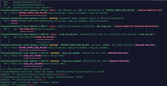
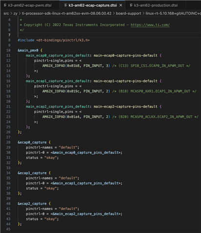
We have customers who need to use the capture function of ecap based on the 08.03.00.07 SDK version, but this version only supports the pwm function of ecap, which cannot meet customer needs. Is there a way to adapt the ti-ecap-capture.c driver to this version of the SDK?

Br,

Hugh

  • Hi Hugh,

    Please move to the latest SDK (v8.6) which has the ECAP capture function support.

  • Bin,

    the user guide is not updated to tell how to use the ecap capture mode, would like to have it.

  • Thanks Tony. Bin is out of office, I have filed a bug against documentation to capture this.

    Regards

    Mukul 

  • Hi Tony,

    I am routing your query to our ECAP module expert for comments.

  • Hello Tony & Hugh,

    For reference of how to set up the ECAP capture in the Linux devicetree, please take a look at the sample devicetree file added in Linux SDK 9.0:
    k3-am625-sk-ecap-capture.dtso

    In terms of how to interact with the ECAP capture functionality from Linux userspace, I am asking the developers to see if they have any examples we can reference. It will probably take a couple of days before we hear back. Please feel free to ping the thread if I do not have another response by the middle of next week.

    Regards,

    Nick

  • Hello Tony & Hugh,

    Here is documentation around how to use the ECAP capture driver:

    The Enhanced Capture (ECAP) module can be used to timestamp events
    detected on signal input pin. It can be used for time measurements
    of pulse train signals.
    
    ECAP module includes 4 timestamp capture registers. For all 4 sequenced
    timestamp capture events (0->1->2->3->0->...), edge polarity (falling/rising
    edge) can be selected.
    
    This driver leverages counter subsystem to :
    - select edge polarity for all 4 capture events (event mode)
    - log timestamps for each capture event
    Event polarity, and CAP0/1/2/3 timestamps give all the information
    about the input pulse train. Further information can easily be computed :
    period and/or duty cycle if frequency is constant, elapsed time between
    pulses, etc...
    
    ...
    
    This series has already been posted (but not merged) to mainline linux :
    https://lore.kernel.org/all/20220923142437.271328-1-jpanis@baylibre.com/
    Some modifications were made to match TI v5.10 kernel.
    
    This series must be applied on top of another series. For more info, reference
    https://lore.kernel.org/all/20220923142437.271328-1-jpanis@baylibre.com
    
    Userspace commands :
    	### CLOCK SIGNAL ###
    	cd /sys/bus/counter/devices/counter0/signal0
    
    	# Get frequency
    	cat frequency
    
    	### INPUT SIGNAL ###
    	cd /sys/bus/counter/devices/counter0/signal1
    
    	# Get available polarities for each capture event
    	cat polarity0_available
    	cat polarity1_available
    	cat polarity2_available
    	cat polarity3_available
    
    	# Get polarity for each capture event
    	cat polarity0
    	cat polarity1
    	cat polarity2
    	cat polarity3
    
    	# Set polarity for each capture event
    	echo positive > polarity0
    	echo negative > polarity1
    	echo positive > polarity2
    	echo negative > polarity3
    
    	### COUNT ###
    	cd /sys/bus/counter/devices/counter0/count0
    
    	# Get ceiling (counter max value)
    	cat ceiling
    
    	# Reset number of overflows & current timebase counter value
    	echo 0 > num_overflows
    	echo 0 > count
    
    	# Run ECAP
    	echo 1 > enable
    
    	# Get number of overflows & current timebase counter value
    	cat num_overflows
    	cat count
    
    	# Get captured timestamps
    	cat capture0
    	cat capture1
    	cat capture2
    	cat capture3
    
    	# Note that counter watches can also be used to get
    	# data from userspace application
    	# -> see tools/counter/counter_example.c
    
    	# Pause ECAP
    	echo 0 > enable
    
    How to test this driver ?
    	1) Device tree modifications
    
    	1.a) k3-am62-main.dtsi
    
    	ecap2: capture@23120000 {
    		compatible = "ti,am62-ecap-capture";
    		reg = <0x00 0x23120000 0x00 0x100>;
    		interrupts = <GIC_SPI 115 IRQ_TYPE_EDGE_RISING>;
    		power-domains = <&k3_pds 53 TI_SCI_PD_EXCLUSIVE>;
    		clocks = <&k3_clks 53 0>;
    		clock-names = "fck";
    	};
    
    	Warning : ecap2 node already used as pwm by default
    	-> must be replaced (as above) or overlayed for capture testing.
    
    	1.b) k3-am625-sk.dts
    
    	&main_pmx0 {
    		main_ecap2_pins_default: main-ecap2-pins-default {
    			pinctrl-single,pins = <
    				AM62X_IOPAD(0x01a4, PIN_INPUT, 2) /* (B20) MCASP0_ACLKX.ECAP2_IN_APWM_OUT */
    			>;
    		};
    	}
    
    	&ecap2 {
    		pinctrl-names = "default";
    		pinctrl-0 = <&main_ecap2_pins_default>;
    		status = "okay";
    	};
    
    	2) Kernel configuration
    
    	Device Drivers  --->
    		<*> Counter support  --->
    			<*>   TI eCAP capture driver
    
    	3) Once ECAP2 is probed, userspace commands can be used as explained above.
    
    	ECAP2 input pin is available on connector J3 pin 11 for square waveform signal.
    
    	For finest testing, this following userspace application code can be run :
    	(stdout MUST be redirected to log file)
    
    	// SPDX-License-Identifier: GPL-2.0-only
    	/* Counter - example userspace application
    	 *
    	 * The userspace application opens /dev/counter0, configures the
    	 * COUNTER_EVENT_CAPTURE event channels to gather count 0 capture
    	 * events, and prints out the data as it becomes available on the
    	 * character device node.
    	 *
    	 * Copyright (C) 2022 Julien Panis
    	 */
    	#include <errno.h>
    	#include <fcntl.h>
    	#include <linux/counter.h>
    	#include <stdio.h>
    	#include <string.h>
    	#include <sys/ioctl.h>
    	#include <unistd.h>
    
    	/* assuming capture attributes are under the count0 directory */
    	#define CAPTURE_WATCH(_id) \
    	{ \
    		.component.type = COUNTER_COMPONENT_EXTENSION, \
    		.component.scope = COUNTER_SCOPE_COUNT, \
    		.component.parent = 0, \
    		.component.id = _id, \
    		.event = COUNTER_EVENT_CAPTURE, \
    		.channel = _id, \
    	}
    
    	/* get id from respective "captureX_component_id" attributes */
    	#define NB_CAP 4
    	static struct counter_watch watches[NB_CAP] = {
    		CAPTURE_WATCH(0),
    		CAPTURE_WATCH(1),
    		CAPTURE_WATCH(2),
    		CAPTURE_WATCH(3),
    	};
    
    	int main(void)
    	{
    		int fd;
    		int ret;
    		int i;
    		struct counter_event event_data[NB_CAP];
    
    		fd = open("/dev/counter0", O_RDWR);
    		if (fd == -1) {
    			perror("Unable to open /dev/counter0");
    			return 1;
    		}
    
    		for (i = 0; i < NB_CAP; i++) {
    			ret = ioctl(fd, COUNTER_ADD_WATCH_IOCTL, watches + i);
    			if (ret == -1) {
    				fprintf(stderr, "Error adding watches[%d]: %s\n", i,
    					strerror(errno));
    				return 1;
    			}
    		}
    		ret = ioctl(fd, COUNTER_ENABLE_EVENTS_IOCTL);
    		if (ret == -1) {
    			perror("Error enabling events");
    			return 1;
    		}
    
    		for (;;) {
    			ret = read(fd, event_data, sizeof(event_data));
    			if (ret == -1) {
    				perror("Failed to read event data");
    				return 1;
    			}
    
    			if (ret != sizeof(event_data)) {
    				fprintf(stderr, "Failed to read event data\n");
    				return -EIO;
    			}
    
    			/* [WARNING] For data consistency analysis, stdout must be redirected to log file !!! */
    			puts("----------");
    			printf("cap0: %llu\n", event_data[0].value);
    			printf("cap1: %llu\n", event_data[1].value);
    			printf("cap2: %llu\n", event_data[2].value);
    			printf("cap3: %llu\n", event_data[3].value);
    		}
    
    		return 0;
    	}
    
    Julien Panis (3):
      dt-bindings: counter: add ti,am62-ecap-capture.yaml
      Documentation: ABI: sysfs-bus-counter: add capture items
      counter: ti-ecap-capture: capture driver support for ECAP
    
     Documentation/ABI/testing/sysfs-bus-counter   |  45 ++
     .../counter/ti,am62-ecap-capture.yaml         |  61 ++
     drivers/counter/Kconfig                       |  15 +
     drivers/counter/Makefile                      |   1 +
     drivers/counter/ti-ecap-capture.c             | 677 ++++++++++++++++++
     include/uapi/linux/counter.h                  |   2 +
     6 files changed, 801 insertions(+)
     create mode 100644 Documentation/devicetree/bindings/counter/ti,am62-ecap-capture.yaml
     create mode 100644 drivers/counter/ti-ecap-capture.c

    From the developer: "For testing, I used the shell commands (also given in the cover letter) along with manually applying the input signal to pin 11 of J3 on the AM62x SK board"

    Regards,

    Nick

  • "Hello, TI expert! Following this guide, I compiled the corresponding patch and applied it, but I encountered the following error. Could you please advise on how to resolve this error?"

  • Hello Li,

    Are you still using Processor SDK 8.3, and trying to backport the ECAP drivers to that version of Linux?

    Please note that we cannot support backporting drivers to earlier versions of Linux on the forums.

    Whatever you are doing, it looks like there are some missing definitions, so the place where those variables / functions are defined either has not been added, or has not been updated.

    If you want to backport the ECAP support on your own (without help from TI), I would probably:

    1) check out the latest version of the ti-linux-kernel repo
    kernel 6.1: https://git.ti.com/cgit/ti-linux-kernel/ti-linux-kernel/tree/?h=ti-linux-6.1.y-cicd
    kernel 5.10: https://git.ti.com/cgit/ti-linux-kernel/ti-linux-kernel/tree/?h=ti-linux-5.10.y-cicd

    2) search for the files where those variables / functions are defined, e.g. grep -r 'ecap_cnt_pm_ops'

    3) check the git log for those files to make sure you are grabbing every single commit that impacts the ecap support

    Even if you do all that, I cannot guarantee that it will work the way you expect in SDK 8.3, since nobody at TI has validated ECAP on that release.

    Regards,

    Nick

  • Thank you for your response. The software version I am currently using is SDK 08.06.00.42. The corresponding device tree for ecap is as follows. Without using the patch you mentioned above, when I output a PWM signal from a signal generator to ecap's input and follow the operation method you described, I always get a value of 0 when using 'cat capture0'.

    What could be causing this issue and is there any solution?

  • Hello Li,

    1) Are you still running into build errors from your reply at https://e2e.ti.com/support/processors-group/processors/f/processors-forum/1242640/am625-ecap/4773577#4773577 ? If so, please give me the terminal commands you are using so I can try to replicate

    2) Are you getting any terminal output during boot time around the ECAP? Please attach it to the thread

    3) Can you please confirm the signal generator settings?

    4) Please attach the terminal output from when you are reading the capture inputs.

    Regards,

    Nick

  • On 5.10/ SDK 8.6

    Relevant patches in kernel to review and explore.

    * ti_config_fragments: connectivity: Enable TI_ECAP_CAPTURE
    * ti_config_fragments: connectivity: Enable TI_ECAP_CAPTURE
    * arm64: dts: ti: Add AM62x SK ECAP Capture overlay
    * arm64: dts: ti: k3-am62-main: Add ECAP capture nodes
    * counter: ti-ecap-capture: capture driver support for ECAP
    * Documentation: ABI: sysfs-bus-counter: add capture items
    * dt-bindings: counter: add ti,am62-ecap-capture.yaml
    * ti_config_fragments: v8_baseport: Enable counter support
  • To simplify the problem, I set ecap0 as the PWM output and ecap1 as the capture input. Additionally, my code does not include the patch file you provided, instead, it uses the original ecap code from SDK 08.06.00.42. Here is the device tree file and config file provided, along with the debugging log. However, even after using the "cat capture0" command, the value obtained is still 0.

    1. dts file

    2. config file

    am62xx_config.zip

    3. debug log

    root@am62xx:/# uname -a
    Linux am62xx 5.10.168-rt83-gc1a1291911 #5 SMP PREEMPT_RT Tue Aug 22 14:33:19 CST 2023 aarch64 GNU/Linux
    
    
    root@am62xx:/# cat /etc/soc_info
    
    Build Time         : Wed Aug 23 09:58:20 CST 2023
    
    sdk_model          : am62xx-sdk-v1.0.0.0
    sdk_uboot          : u-boot-2021.01+gitAUTOINC+2ee8efd654-g2ee8efd654
    sdk_kernel         : linux-rt-5.10.168+gitAUTOINC+c1a1291911-gc1a1291911
    sdk_atf            : trusted-firmware-a-2.8+gitAUTOINC+2fcd408bb3
    sdk_tee            : optee_os-3.20.0
    sdk_device_type    : hs
    
    cpu_model          : AM6234ATCGHAALW,FCCSP-425,TI
    cpu_security       : y
    cpu_3d_graphics    : n
    cpu_linux_dtb      : k3-am6234-sk-sec.dtb
    
    
    root@am62xx:/# journalctl | grep cap
    Jun 16 09:57:23 am62xx kernel: videodev: Linux video capture interface: v2.00
    Jun 16 09:57:30 am62xx /usr/sbin/irqbalance[840]: No directory /sys/devices/platform/23110000.capture/: No such file or directory
    Jun 16 09:57:30 am62xx /usr/sbin/irqbalance[840]: IRQ 23110000.capture(51) guessed as class 0
    Jun 16 09:57:31 am62xx avahi-daemon[866]: Successfully dropped remaining capabilities.
    
    
    root@am62xx:/# journalctl | grep pwm
    Jun 16 09:57:23 am62xx kernel: pwm-beeper buzzer: supply amp not found, using dummy regulator
    Jun 16 09:57:23 am62xx kernel: input: pwm-beeper as /devices/platform/buzzer/input/input0
    Jun 16 09:57:23 am62xx kernel: pwm-backlight backlight: supply power not found, using dummy regulator
    
    
    root@am62xx:/# lsmod | grep ecap
    ti_ecap_capture        20480  0
    counter                28672  1 ti_ecap_capture
    
    
    root@am62xx:/# cd /sys/firmware/devicetree/base/bus@f0000
    root@am62xx:/sys/firmware/devicetree/base/bus@f0000# ll *pwm*
    pwm@23000000:
    -r--r--r--    1 root     root             4 Jun 16 10:02 #pwm-cells
    -r--r--r--    1 root     root            10 Jun 16 10:02 clock-names
    -r--r--r--    1 root     root            20 Jun 16 10:02 clocks
    -r--r--r--    1 root     root            30 Jun 16 10:02 compatible
    -r--r--r--    1 root     root             4 Jun 16 10:02 name
    -r--r--r--    1 root     root             4 Jun 16 10:02 phandle
    -r--r--r--    1 root     root            12 Jun 16 10:02 power-domains
    -r--r--r--    1 root     root            16 Jun 16 10:02 reg
    -r--r--r--    1 root     root             5 Jun 16 10:02 status
    
    pwm@23010000:
    -r--r--r--    1 root     root             4 Jun 16 10:02 #pwm-cells
    -r--r--r--    1 root     root            10 Jun 16 10:02 clock-names
    -r--r--r--    1 root     root            20 Jun 16 10:02 clocks
    -r--r--r--    1 root     root            30 Jun 16 10:02 compatible
    -r--r--r--    1 root     root             4 Jun 16 10:02 name
    -r--r--r--    1 root     root             4 Jun 16 10:02 phandle
    -r--r--r--    1 root     root            12 Jun 16 10:02 power-domains
    -r--r--r--    1 root     root            16 Jun 16 10:02 reg
    -r--r--r--    1 root     root             5 Jun 16 10:02 status
    
    pwm@23020000:
    -r--r--r--    1 root     root             4 Jun 16 10:02 #pwm-cells
    -r--r--r--    1 root     root            10 Jun 16 10:02 clock-names
    -r--r--r--    1 root     root            20 Jun 16 10:02 clocks
    -r--r--r--    1 root     root            30 Jun 16 10:02 compatible
    -r--r--r--    1 root     root             4 Jun 16 10:02 name
    -r--r--r--    1 root     root             4 Jun 16 10:02 phandle
    -r--r--r--    1 root     root            12 Jun 16 10:02 power-domains
    -r--r--r--    1 root     root            16 Jun 16 10:02 reg
    -r--r--r--    1 root     root             9 Jun 16 10:02 status
    
    pwm@23100000:
    -r--r--r--    1 root     root             4 Jun 16 10:02 #pwm-cells
    -r--r--r--    1 root     root             4 Jun 16 10:02 clock-names
    -r--r--r--    1 root     root            12 Jun 16 10:02 clocks
    -r--r--r--    1 root     root            15 Jun 16 10:02 compatible
    -r--r--r--    1 root     root             4 Jun 16 10:02 name
    -r--r--r--    1 root     root             4 Jun 16 10:02 phandle
    -r--r--r--    1 root     root             4 Jun 16 10:02 pinctrl-0
    -r--r--r--    1 root     root             8 Jun 16 10:02 pinctrl-names
    -r--r--r--    1 root     root            12 Jun 16 10:02 power-domains
    -r--r--r--    1 root     root            16 Jun 16 10:02 reg
    -r--r--r--    1 root     root             5 Jun 16 10:02 status
    
    pwm@23110000:
    -r--r--r--    1 root     root             4 Jun 16 10:02 #pwm-cells
    -r--r--r--    1 root     root             4 Jun 16 10:02 clock-names
    -r--r--r--    1 root     root            12 Jun 16 10:02 clocks
    -r--r--r--    1 root     root            15 Jun 16 10:02 compatible
    -r--r--r--    1 root     root             4 Jun 16 10:02 name
    -r--r--r--    1 root     root             4 Jun 16 10:02 phandle
    -r--r--r--    1 root     root             4 Jun 16 10:02 pinctrl-0
    -r--r--r--    1 root     root             8 Jun 16 10:02 pinctrl-names
    -r--r--r--    1 root     root            12 Jun 16 10:02 power-domains
    -r--r--r--    1 root     root            16 Jun 16 10:02 reg
    -r--r--r--    1 root     root             9 Jun 16 10:02 status
    
    pwm@23120000:
    -r--r--r--    1 root     root             4 Jun 16 10:02 #pwm-cells
    -r--r--r--    1 root     root             4 Jun 16 10:02 clock-names
    -r--r--r--    1 root     root            12 Jun 16 10:02 clocks
    -r--r--r--    1 root     root            15 Jun 16 10:02 compatible
    -r--r--r--    1 root     root             4 Jun 16 10:02 name
    -r--r--r--    1 root     root             4 Jun 16 10:02 phandle
    -r--r--r--    1 root     root             4 Jun 16 10:02 pinctrl-0
    -r--r--r--    1 root     root             8 Jun 16 10:02 pinctrl-names
    -r--r--r--    1 root     root            12 Jun 16 10:02 power-domains
    -r--r--r--    1 root     root            16 Jun 16 10:02 reg
    -r--r--r--    1 root     root             9 Jun 16 10:02 status
    
    
    root@am62xx:/sys/firmware/devicetree/base/bus@f0000# hexdump -C pwm@23100000/status
    00000000  6f 6b 61 79 00                                    |okay.|
    00000005
    
    root@am62xx:/sys/firmware/devicetree/base/bus@f0000# hexdump -C pwm@23110000/status
    00000000  64 69 73 61 62 6c 65 64  00                       |disabled.|
    00000009
    
    root@am62xx:/sys/firmware/devicetree/base/bus@f0000# hexdump -C pwm@23120000/status
    00000000  64 69 73 61 62 6c 65 64  00                       |disabled.|
    00000009
    
    
    root@am62xx:/sys/firmware/devicetree/base/bus@f0000# cat /sys/kernel/debug/pwm
    
    platform/23010000.pwm, 2 PWM devices
     pwm-0   ((null)              ): period: 0 ns duty: 0 ns polarity: normal
     pwm-1   (backlight           ): requested enabled period: 25000 ns duty: 19607 ns polarity: normal
    
    platform/23000000.pwm, 2 PWM devices
     pwm-0   (buzzer              ): requested period: 366166 ns duty: 183083 ns polarity: normal
     pwm-1   ((null)              ): period: 0 ns duty: 0 ns polarity: normal
    
    platform/23100000.pwm, 1 PWM device
     pwm-0   ((null)              ): period: 0 ns duty: 0 ns polarity: normal


    root@am62xx:/sys/firmware/devicetree/base/bus@f0000# ll /sys/class/pwm
    lrwxrwxrwx    1 root     root             0 Jun 16 09:57 pwmchip0 -> ../../devices/platform/bus@f0000/23100000.pwm/pwm/pwmchip0
    lrwxrwxrwx    1 root     root             0 Jun 16 09:57 pwmchip1 -> ../../devices/platform/bus@f0000/23000000.pwm/pwm/pwmchip1
    lrwxrwxrwx    1 root     root             0 Jun 16 09:57 pwmchip3 -> ../../devices/platform/bus@f0000/23010000.pwm/pwm/pwmchip3


    root@am62xx:/sys/class/pwm/pwmchip0# base/bus@f0000# cd /sys/class/pwm/pwmchip0/
    root@am62xx:/sys/class/pwm/pwmchip0# cat npwm
    1
    root@am62xx:/sys/class/pwm/pwmchip0# echo 0 > export
    root@am62xx:/sys/class/pwm/pwmchip0# cd pwm0
    root@am62xx:/sys/class/pwm/pwmchip0/pwm0# echo 100000000 > period
    root@am62xx:/sys/class/pwm/pwmchip0/pwm0# echo 30000000 > duty_cycle
    root@am62xx:/sys/class/pwm/pwmchip0/pwm0# echo "inversed" > polarity
    root@am62xx:/sys/class/pwm/pwmchip0/pwm0# echo 1 > enable
    
    root@am62xx:/sys/class/pwm/pwmchip0/pwm0# cat /sys/kernel/debug/pwm
    platform/23010000.pwm, 2 PWM devices
     pwm-0   ((null)              ): period: 0 ns duty: 0 ns polarity: normal
     pwm-1   (backlight           ): requested enabled period: 25000 ns duty: 19607 ns polarity: normal
    
    platform/23000000.pwm, 2 PWM devices
     pwm-0   (buzzer              ): requested period: 366166 ns duty: 183083 ns polarity: normal
     pwm-1   ((null)              ): period: 0 ns duty: 0 ns polarity: normal
    
    platform/23100000.pwm, 1 PWM device
     pwm-0   (sysfs               ): requested enabled period: 100000000 ns duty: 30000000 ns polarity: inverse


    root@am62xx:/sys/class/pwm/pwmchip0/pwm0# cd /sys/firmware/devicetree/base/bus@f0000
    
    root@am62xx:/sys/firmware/devicetree/base/bus@f0000# ll *capture*
    capture@23100000:
    -r--r--r--    1 root     root             4 Jun 16 10:04 clock-names
    -r--r--r--    1 root     root            12 Jun 16 10:04 clocks
    -r--r--r--    1 root     root            21 Jun 16 10:04 compatible
    -r--r--r--    1 root     root            12 Jun 16 10:04 interrupts
    -r--r--r--    1 root     root             8 Jun 16 10:04 name
    -r--r--r--    1 root     root             4 Jun 16 10:04 phandle
    -r--r--r--    1 root     root             4 Jun 16 10:04 pinctrl-0
    -r--r--r--    1 root     root             8 Jun 16 10:04 pinctrl-names
    -r--r--r--    1 root     root            12 Jun 16 10:04 power-domains
    -r--r--r--    1 root     root            16 Jun 16 10:04 reg
    -r--r--r--    1 root     root             9 Jun 16 10:04 status
    
    capture@23110000:
    -r--r--r--    1 root     root             4 Jun 16 10:04 clock-names
    -r--r--r--    1 root     root            12 Jun 16 10:04 clocks
    -r--r--r--    1 root     root            21 Jun 16 10:04 compatible
    -r--r--r--    1 root     root            12 Jun 16 10:04 interrupts
    -r--r--r--    1 root     root             8 Jun 16 10:04 name
    -r--r--r--    1 root     root             4 Jun 16 10:04 phandle
    -r--r--r--    1 root     root             4 Jun 16 10:04 pinctrl-0
    -r--r--r--    1 root     root             8 Jun 16 10:04 pinctrl-names
    -r--r--r--    1 root     root            12 Jun 16 10:04 power-domains
    -r--r--r--    1 root     root            16 Jun 16 10:04 reg
    -r--r--r--    1 root     root             5 Jun 16 10:04 status
    
    capture@23120000:
    -r--r--r--    1 root     root             4 Jun 16 10:04 clock-names
    -r--r--r--    1 root     root            12 Jun 16 10:04 clocks
    -r--r--r--    1 root     root            21 Jun 16 10:04 compatible
    -r--r--r--    1 root     root            12 Jun 16 10:04 interrupts
    -r--r--r--    1 root     root             8 Jun 16 10:04 name
    -r--r--r--    1 root     root             4 Jun 16 10:04 phandle
    -r--r--r--    1 root     root             4 Jun 16 10:04 pinctrl-0
    -r--r--r--    1 root     root             8 Jun 16 10:04 pinctrl-names
    -r--r--r--    1 root     root            12 Jun 16 10:04 power-domains
    -r--r--r--    1 root     root            16 Jun 16 10:04 reg
    -r--r--r--    1 root     root             9 Jun 16 10:04 status
    
    /status62xx:/sys/firmware/devicetree/base/bus@f0000# hexdump -C capture@23100000/
    00000000  64 69 73 61 62 6c 65 64  00                       |disabled.|
    00000009
    root@am62xx:/sys/firmware/devicetree/base/bus@f0000#
    /status62xx:/sys/firmware/devicetree/base/bus@f0000# hexdump -C capture@23110000/
    00000000  6f 6b 61 79 00                                    |okay.|
    00000005
    root@am62xx:/sys/firmware/devicetree/base/bus@f0000#
    /status62xx:/sys/firmware/devicetree/base/bus@f0000# hexdump -C capture@23120000/
    00000000  64 69 73 61 62 6c 65 64  00                       |disabled.|
    00000009


    root@am62xx:/sys/firmware/devicetree/base/bus@f0000# cat /proc/interrupts | grep capture
     51:          0          0          0          0     GICv3 146 Edge      23110000.capture
    
    
    root@am62xx:/sys/firmware/devicetree/base/bus@f0000# ll /dev/counter0
    crw-------    1 root     root      236,   0 Jun 16 09:57 /dev/counter0


    /oot@am62xx:/sys/firmware/devicetree/base/bus@f0000# ll /sys/bus/counter/devices/
    lrwxrwxrwx    1 root     root             0 Jun 16 09:57 counter0 -> ../../../devices/platform/bus@f0000/23110000.capture/counter0
    
    
    root@am62xx:/sys/firmware/devicetree/base/bus@f0000# cd /sys/bus/counter/devices/counter0
    root@am62xx:/sys/bus/counter/devices/counter0# ll
    drwxr-xr-x    2 root     root             0 Jun 16 10:05 count0
    -r--r--r--    1 root     root          4096 Jun 16 10:05 dev
    -rw-r--r--    1 root     root          4096 Jun 16 10:05 events_queue_size
    -r--r--r--    1 root     root          4096 Jun 16 10:05 name
    -r--r--r--    1 root     root          4096 Jun 16 10:05 num_counts
    -r--r--r--    1 root     root          4096 Jun 16 10:05 num_signals
    lrwxrwxrwx    1 root     root             0 Jun 16 10:05 of_node -> ../../../../../firmware/devicetree/base/bus@f0000/capture@23110000
    drwxr-xr-x    2 root     root             0 Jun 16 10:05 power
    drwxr-xr-x    2 root     root             0 Jun 16 10:05 signal0
    drwxr-xr-x    2 root     root             0 Jun 16 09:58 signal1
    lrwxrwxrwx    1 root     root             0 Jun 16 09:57 subsystem -> ../../../../../bus/counter
    -rw-r--r--    1 root     root          4096 Jun 16 09:57 uevent
    
    
    root@am62xx:/sys/bus/counter/devices/counter0# ll /sys/bus/counter/devices/counter0/count0
    -rw-r--r--    1 root     root          4096 Jun 16 10:05 capture0
    -r--r--r--    1 root     root          4096 Jun 16 10:05 capture0_component_id
    -rw-r--r--    1 root     root          4096 Jun 16 10:05 capture1
    -r--r--r--    1 root     root          4096 Jun 16 10:05 capture1_component_id
    -rw-r--r--    1 root     root          4096 Jun 16 10:05 capture2
    -r--r--r--    1 root     root          4096 Jun 16 10:05 capture2_component_id
    -rw-r--r--    1 root     root          4096 Jun 16 10:05 capture3
    -r--r--r--    1 root     root          4096 Jun 16 10:05 capture3_component_id
    -r--r--r--    1 root     root          4096 Jun 16 10:05 ceiling
    -r--r--r--    1 root     root          4096 Jun 16 10:05 ceiling_component_id
    -rw-r--r--    1 root     root          4096 Jun 16 10:05 count
    -rw-r--r--    1 root     root          4096 Jun 16 10:05 enable
    -r--r--r--    1 root     root          4096 Jun 16 10:05 enable_component_id
    -r--r--r--    1 root     root          4096 Jun 16 10:05 function
    -r--r--r--    1 root     root          4096 Jun 16 10:05 function_available
    -r--r--r--    1 root     root          4096 Jun 16 10:05 name
    -rw-r--r--    1 root     root          4096 Jun 16 10:05 num_overflows
    -r--r--r--    1 root     root          4096 Jun 16 10:05 num_overflows_component_id
    -r--r--r--    1 root     root          4096 Jun 16 10:05 signal0_action
    -r--r--r--    1 root     root          4096 Jun 16 10:05 signal0_action_available
    -r--r--r--    1 root     root          4096 Jun 16 10:05 signal0_action_component_id
    -r--r--r--    1 root     root          4096 Jun 16 10:05 signal1_action
    -r--r--r--    1 root     root          4096 Jun 16 10:05 signal1_action_available
    -r--r--r--    1 root     root          4096 Jun 16 10:05 signal1_action_component_id
    
    
    root@am62xx:/sys/bus/counter/devices/counter0# ll /sys/bus/counter/devices/counter0/signal0/
    -r--r--r--    1 root     root          4096 Jun 16 10:05 frequency
    -r--r--r--    1 root     root          4096 Jun 16 10:05 frequency_component_id
    -r--r--r--    1 root     root          4096 Jun 16 10:05 name
    ----------    1 root     root          4096 Jun 16 10:05 signal
    
    root@am62xx:/sys/bus/counter/devices/counter0# ll /sys/bus/counter/devices/counter0/signal1/
    -r--r--r--    1 root     root          4096 Jun 16 09:58 name
    -rw-r--r--    1 root     root          4096 Jun 16 09:58 polarity0
    -r--r--r--    1 root     root          4096 Jun 16 09:58 polarity0_available
    -r--r--r--    1 root     root          4096 Jun 16 09:58 polarity0_component_id
    -rw-r--r--    1 root     root          4096 Jun 16 09:58 polarity1
    -r--r--r--    1 root     root          4096 Jun 16 09:58 polarity1_available
    -r--r--r--    1 root     root          4096 Jun 16 09:58 polarity1_component_id
    -rw-r--r--    1 root     root          4096 Jun 16 09:58 polarity2
    -r--r--r--    1 root     root          4096 Jun 16 09:58 polarity2_available
    -r--r--r--    1 root     root          4096 Jun 16 09:58 polarity2_component_id
    -rw-r--r--    1 root     root          4096 Jun 16 09:58 polarity3
    -r--r--r--    1 root     root          4096 Jun 16 09:58 polarity3_available
    -r--r--r--    1 root     root          4096 Jun 16 09:58 polarity3_component_id
    ----------    1 root     root          4096 Jun 16 09:58 signal
    
    
    root@am62xx:/sys/bus/counter/devices/counter0# cd /sys/bus/counter/devices/counter0/signal0
    root@am62xx:/sys/bus/counter/devices/counter0/signal0# cat frequency
    125000000
    
    root@am62xx:/signal1s/counter/devices/counter0/signal0# cd /sys/bus/counter/devices/counter0/signal1
    root@am62xx:/sys/bus/counter/devices/counter0/signal1# cat polarity0_available
    positive
    negative
    root@am62xx:/sys/bus/counter/devices/counter0/signal1# cat polarity1_available
    positive
    negative
    root@am62xx:/sys/bus/counter/devices/counter0/signal1# cat polarity2_available
    positive
    negative
    root@am62xx:/sys/bus/counter/devices/counter0/signal1# cat polarity3_available
    positive
    negative
    root@am62xx:/sys/bus/counter/devices/counter0/signal1# cat polarity0
    positive
    root@am62xx:/sys/bus/counter/devices/counter0/signal1# cat polarity1
    positive
    root@am62xx:/sys/bus/counter/devices/counter0/signal1# cat polarity2
    positive
    root@am62xx:/sys/bus/counter/devices/counter0/signal1# cat polarity3
    positive
    root@am62xx:/sys/bus/counter/devices/counter0/signal1# echo positive > polarity0
    root@am62xx:/sys/bus/counter/devices/counter0/signal1# echo negative > polarity1
    root@am62xx:/sys/bus/counter/devices/counter0/signal1# echo positive > polarity2
    root@am62xx:/sys/bus/counter/devices/counter0/signal1# echo negative > polarity3
    root@am62xx:/sys/bus/counter/devices/counter0/signal1# cat polarity0
    positive
    root@am62xx:/sys/bus/counter/devices/counter0/signal1# cat polarity1
    negative
    root@am62xx:/sys/bus/counter/devices/counter0/signal1# cat polarity2
    positive
    root@am62xx:/sys/bus/counter/devices/counter0/signal1# cat polarity3
    negative
    
    
    root@am62xx:/sys/bus/counter/devices/counter0/signal1# cd /sys/bus/counter/devices/counter0/count0
    root@am62xx:/sys/bus/counter/devices/counter0/count0# cat ceiling
    4294967295
    root@am62xx:/sys/bus/counter/devices/counter0/count0# echo 0 > num_overflows
    root@am62xx:/sys/bus/counter/devices/counter0/count0# echo 0 > count
    root@am62xx:/sys/bus/counter/devices/counter0/count0# echo 1 > enable
    root@am62xx:/sys/bus/counter/devices/counter0/count0# cat num_overflows
    0
    root@am62xx:/sys/bus/counter/devices/counter0/count0# cat count
    1398114814
    root@am62xx:/sys/bus/counter/devices/counter0/count0# cat capture0
    0
    root@am62xx:/sys/bus/counter/devices/counter0/count0# cat capture1
    0
    root@am62xx:/sys/bus/counter/devices/counter0/count0# cat capture2
    0
    root@am62xx:/sys/bus/counter/devices/counter0/count0# cat capture3
    0


  • Hello Li,

    Have you verified that you are actually seeing an output on the ECAP PWM output?

    When I reference other devicetree files like k3-am642-evm.dts, it looks like the pinmux settings for ECAP PWM output are still set to PIN_INPUT, even though it is an output signal. I have not had time to check on my side whether PIN_INPUT vs PIN_OUTPUT makes a difference in this usecase.

    Regards,

    Nick

  • Hello Nick,

    I measured the ECAP PWM output using an oscilloscope, and the measurement results are shown in the following figure. 

    root@am62xx:/sys/class/pwm/pwmchip0# base/bus@f0000# cd /sys/class/pwm/pwmchip0/
    root@am62xx:/sys/class/pwm/pwmchip0# cat npwm
    1
    root@am62xx:/sys/class/pwm/pwmchip0# echo 0 > export
    root@am62xx:/sys/class/pwm/pwmchip0# cd pwm0
    root@am62xx:/sys/class/pwm/pwmchip0/pwm0# echo 100000000 > period
    root@am62xx:/sys/class/pwm/pwmchip0/pwm0# echo 30000000 > duty_cycle
    root@am62xx:/sys/class/pwm/pwmchip0/pwm0# echo "inversed" > polarity
    root@am62xx:/sys/class/pwm/pwmchip0/pwm0# echo 1 > enable
    
    root@am62xx:/sys/class/pwm/pwmchip0/pwm0# cat /sys/kernel/debug/pwm
    platform/23010000.pwm, 2 PWM devices
     pwm-0   ((null)              ): period: 0 ns duty: 0 ns polarity: normal
     pwm-1   (backlight           ): requested enabled period: 25000 ns duty: 19607 ns polarity: normal
    
    platform/23000000.pwm, 2 PWM devices
     pwm-0   (buzzer              ): requested period: 366166 ns duty: 183083 ns polarity: normal
     pwm-1   ((null)              ): period: 0 ns duty: 0 ns polarity: normal
    
    platform/23100000.pwm, 1 PWM device
     pwm-0   (sysfs               ): requested enabled period: 100000000 ns duty: 30000000 ns polarity: inverse

    Taking into account the above commands, the analysis reveals that the PWM has output a waveform that meets the expected requirements.

    So why is the ecap still not working properly even though the pwm is outputting correctly?

    Regards,

    Li

  • Hello Li,

    I am going to try to replicate your results on my side tomorrow.

    Are you testing on a TI EVM, or on a custom board?

    Regards,

    Nick

  • on a custom board

  • any updates today?

  • Hello Li,

    I apologize for the continued delayed response. Will try to run tests tomorrow.

    In the meantime, can you please clarify for me exactly how the ecap-pwm, ecap-capture, and production.dtsi device tree files are related to each other?

    Please include each file, and the "includes" in each file. Also, I assume there is a 4th file that ends in .dts that includes even production.dtsi?

    For each device tree file, please type out:

    filename
    includes
    pwm settings

    Please remember that devicetrees are read from top to bottom. e.g., if your top-level .dts file includes the 3 .dtsi files like this:
    ecap-pwm.dtsi
    ecap-capture.dtsi
    production.dtsi

    then the settings in production.dtsi would overwrite the settings in the earlier included files. However, if you did it like this in your top-level .dts file:

    production.dtsi
    ecap-capture.dtsi
    ecap-pwm.dtsi

    Then the settings in ecap-pwm would overwrite the settings in the earlier files, and the PWM output would be enabled for every ecap instance instead of enabling PWM for one instance, and Capture for another instance.

    Regards,

    Nick

  • Just wanted to let you know that I have been spending time on getting a hardware setup going that I can run tests on. I do not have working code yet. Will provide another update on Thursday or Friday.

    Regards,

    Nick

  • root@am62xx:/sys/bus/counter/devices/counter0/count0# cat count
    1398114814
    root@am62xx:/sys/bus/counter/devices/counter0/count0# cat capture0
    42461133
    root@am62xx:/sys/bus/counter/devices/counter0/count0# cat capture1
    51211134
    root@am62xx:/sys/bus/counter/devices/counter0/count0# cat capture2
    54961134
    root@am62xx:/sys/bus/counter/devices/counter0/count0# cat capture3
    88711137

    Hello Nick,

    If I have the above output, how do I calculate the duty cycle and period of PWM?

    Regards,

    LI

  • Hello Li,

    Glad to see that you are able to capture inputs now! Did anything change?

    For hardware setup, I connected ECAP0 PWM output to ECAP2 capture on the AM62-SKB on the J3 header. See pinmuxing below, and search for the pin numbers on the EVM schematic to find the J3 pins.

    Devicetree changes:

    &main_pmx0 {
    ...
            main_ecap0_pwm_pins_default: main-ecap0-pwm-pins-default {
                    pinctrl-single,pins = <
                            AM62X_IOPAD(0x01b8, PIN_OUTPUT, 3) /* (C13) SPI0_CS1.ECAP0_IN_APWM_OUT */
                    >;
            };
            main_ecap2_capture_pins_default: main-ecap2-capture-pins-default {
                    pinctrl-single,pins = <
                            AM62X_IOPAD(0x01a4, PIN_INPUT, 2) /* (B20) MCASP0_ACLKX.ECAP2_IN_APWM_OUT */
                    >;
            };
    
    };
    
    &ecap0_pwm {
            pinctrl-names = "default";
            pinctrl-0 = <&main_ecap0_pwm_pins_default>;
            status = "okay";
    };
    
    &ecap2_pwm {
            status = "disabled";
    };
    
    &ecap2_capture {
            pinctrl-names = "default";
            pinctrl-0 = <&main_ecap2_capture_pins_default>;
            status = "okay";
    };
    

    When I finished the test on my side, I was able to see the inputs as expected:

    root@am62xx-evm:/sys/bus/counter/devices/counter0/count0# uname -a
    Linux am62xx-evm 5.10.168-g2c23e6c538 #1 SMP PREEMPT Fri Feb 24 05:59:04 UTC 2023 aarch64 aarch64 aarch64 GNU/Linux
    
    // check ECAP PWM output and ECAP capture input
    root@am62xx-evm:~# cat /proc/device-tree/__symbols__/ecap0_pwm
    /bus@f0000/pwm@23100000
    root@am62xx-evm:~# cat /proc/device-tree/bus@f0000/pwm@23100000/status
    okay
    root@am62xx-evm:~#
    cat /proc/device-tree/__symbols__/ecap2_capture
    /bus@f0000/capture@23120000root@am62xx-evm:~# cat /proc/device-tree/bus@f0000/capture@23120000/status
    okay
    
    // set PWM output exactly as you did
    
    // set capture input exactly as described in the nodes at the top of this e2e thread
    
    root@am62xx-evm:/sys/bus/counter/devices/counter0/count0# echo 0 > num_overflows
    root@am62xx-evm:/sys/bus/counter/devices/counter0/count0# echo 0 > count
    root@am62xx-evm:/sys/bus/counter/devices/counter0/count0# echo 1 > enable
    root@am62xx-evm:/sys/bus/counter/devices/counter0/count0# cat num_overflows
    0
    root@am62xx-evm:/sys/bus/counter/devices/counter0/count0# cat count
    1057336545
    root@am62xx-evm:/sys/bus/counter/devices/counter0/count0# cat count
    1361843282
    root@am62xx-evm:/sys/bus/counter/devices/counter0/count0# cat count
    1508350869
    root@am62xx-evm:/sys/bus/counter/devices/counter0/count0# cat count
    1629343053
    root@am62xx-evm:/sys/bus/counter/devices/counter0/count0# cat count
    1756358067
    root@am62xx-evm:/sys/bus/counter/devices/counter0/count0# cat capture0
    2102288297
    root@am62xx-evm:/sys/bus/counter/devices/counter0/count0# cat capture1
    2464788326
    root@am62xx-evm:/sys/bus/counter/devices/counter0/count0# cat capture2
    2777288351
    root@am62xx-evm:/sys/bus/counter/devices/counter0/count0# cat capture2
    3227288387

    You will not be able to get useful duty cycle/PWM period information from hand-typing out stuff. I would use a program to read all 4 entries at once, as shown above: https://e2e.ti.com/support/processors-group/processors/f/processors-forum/1242640/am625-ecap/4766153#4766153

    If the captures are set to trigger on alternating polarity, that tells you the time for the high part of the duty cycle, and the low part of the duty cycle. Then you can calculate the duty cycle and the frequency from those 4 datapoints.

    Regards,

    Nick

  • Hello Nick,

    I obtained the following information from this link: https://e2e.ti.com/support/processors-group/processors/f/processors-forum/1242640/am625-ecap/4766153#4766153

    The Enhanced Capture (ECAP) module can be used to timestamp events
    detected on signal input pin. It can be used for time measurements
    of pulse train signals.
    
    ECAP module includes 4 timestamp capture registers. For all 4 sequenced
    timestamp capture events (0->1->2->3->0->...), edge polarity (falling/rising
    edge) can be selected.
    
    This driver leverages counter subsystem to :
    - select edge polarity for all 4 capture events (event mode)
    - log timestamps for each capture event
    Event polarity, and CAP0/1/2/3 timestamps give all the information
    about the input pulse train. Further information can easily be computed :
    period and/or duty cycle if frequency is constant, elapsed time between
    pulses, etc...
    
    ...
    

    There is no explanation here about the method to calculate the duty cycle and period of PWM from the values of capture0~capture3.

    Could you provide an example program that calculates the duty cycle and period of PWM from the values of capture0~capture3?

    Regards,

    LI

  • Hello Li,

    We are starting to get outside the scope of what you can ask TI to support. But here is a quick reminder about how duty cycle and period are defined. You can write your own code.

    Let's say capture0 rising edge, capture1 falling edge, capture2 rising edge, capture3 falling edge.

    Then period = capture2 - capture0 (or average that with capture3 - capture1)

    The signal is high for capture1 - capture0

    the high part of the duty cycle is signal_high_time / period

    Regards,

    Nick

  • Hi Nick,

    I have test ecap with the application you mentioned above, and the code of the application is as follows:

    	// SPDX-License-Identifier: GPL-2.0-only
    	/* Counter - example userspace application
    	 *
    	 * The userspace application opens /dev/counter0, configures the
    	 * COUNTER_EVENT_CAPTURE event channels to gather count 0 capture
    	 * events, and prints out the data as it becomes available on the
    	 * character device node.
    	 *
    	 * Copyright (C) 2022 Julien Panis
    	 */
    	#include <errno.h>
    	#include <fcntl.h>
    	#include <linux/counter.h>
    	#include <stdio.h>
    	#include <string.h>
    	#include <sys/ioctl.h>
    	#include <unistd.h>
    
    	/* assuming capture attributes are under the count0 directory */
    	#define CAPTURE_WATCH(_id) \
    	{ \
    		.component.type = COUNTER_COMPONENT_EXTENSION, \
    		.component.scope = COUNTER_SCOPE_COUNT, \
    		.component.parent = 0, \
    		.component.id = _id, \
    		.event = COUNTER_EVENT_CAPTURE, \
    		.channel = _id, \
    	}
    
    	/* get id from respective "captureX_component_id" attributes */
    	#define NB_CAP 4
    	static struct counter_watch watches[NB_CAP] = {
    		CAPTURE_WATCH(0),
    		CAPTURE_WATCH(1),
    		CAPTURE_WATCH(2),
    		CAPTURE_WATCH(3),
    	};
    
    	int main(void)
    	{
    		int fd;
    		int ret;
    		int i;
    		struct counter_event event_data[NB_CAP];
    
    		fd = open("/dev/counter0", O_RDWR);
    		if (fd == -1) {
    			perror("Unable to open /dev/counter0");
    			return 1;
    		}
    
    		for (i = 0; i < NB_CAP; i++) {
    			ret = ioctl(fd, COUNTER_ADD_WATCH_IOCTL, watches + i);
    			if (ret == -1) {
    				fprintf(stderr, "Error adding watches[%d]: %s\n", i,
    					strerror(errno));
    				return 1;
    			}
    		}
    		ret = ioctl(fd, COUNTER_ENABLE_EVENTS_IOCTL);
    		if (ret == -1) {
    			perror("Error enabling events");
    			return 1;
    		}
    
    		for (;;) {
    			ret = read(fd, event_data, sizeof(event_data));
    			if (ret == -1) {
    				perror("Failed to read event data");
    				return 1;
    			}
    
    			if (ret != sizeof(event_data)) {
    				fprintf(stderr, "Failed to read event data\n");
    				return -EIO;
    			}
    
    			/* [WARNING] For data consistency analysis, stdout must be redirected to log file !!! */
    			puts("----------");
    			printf("cap0: %llu\n", event_data[0].value);
    			printf("cap1: %llu\n", event_data[1].value);
    			printf("cap2: %llu\n", event_data[2].value);
    			printf("cap3: %llu\n", event_data[3].value);
    		}
    
    		return 0;
    	}

    The commands used during testing are as follows:

    root@am62xx:/opt# cd /sys/class/pwm/pwmchip0
    root@am62xx:/sys/class/pwm/pwmchip0#
    root@am62xx:/sys/class/pwm/pwmchip0# echo 0 > export
    root@am62xx:/sys/class/pwm/pwmchip0#
    root@am62xx:/sys/class/pwm/pwmchip0# cd pwm0/
    root@am62xx:/sys/class/pwm/pwmchip0/pwm0#
    root@am62xx:/sys/class/pwm/pwmchip0/pwm0# echo 100000000 > period
    root@am62xx:/sys/class/pwm/pwmchip0/pwm0#
    root@am62xx:/sys/class/pwm/pwmchip0/pwm0# echo 30000000 > duty_cycle
    root@am62xx:/sys/class/pwm/pwmchip0/pwm0#
    root@am62xx:/sys/class/pwm/pwmchip0/pwm0# echo "inversed" > polarity
    root@am62xx:/sys/class/pwm/pwmchip0/pwm0#
    root@am62xx:/sys/class/pwm/pwmchip0/pwm0# echo 1 > enable
    root@am62xx:/sys/class/pwm/pwmchip0/pwm0#
    root@am62xx:/sys/class/pwm/pwmchip0/pwm0# cat /sys/kernel/debug/pwm
    platform/23010000.pwm, 2 PWM devices
     pwm-0   ((null)              ): period: 0 ns duty: 0 ns polarity: normal
     pwm-1   (backlight           ): requested enabled period: 25000 ns duty: 19607 ns polarity: normal
    
    platform/23000000.pwm, 2 PWM devices
     pwm-0   (buzzer              ): requested period: 366166 ns duty: 0 ns polarity: normal
     pwm-1   ((null)              ): period: 0 ns duty: 0 ns polarity: normal
    
    platform/23100000.pwm, 1 PWM device
     pwm-0   (sysfs               ): requested enabled period: 100000000 ns duty: 30000000 ns polarity: inverse
    root@am62xx:/sys/class/pwm/pwmchip0/pwm0#
    root@am62xx:/sys/class/pwm/pwmchip0/pwm0# cd /sys/bus/counter/devices/counter0/signal1
    root@am62xx:/sys/bus/counter/devices/counter0/signal1#
    root@am62xx:/sys/bus/counter/devices/counter0/signal1# echo positive > polarity0
    root@am62xx:/sys/bus/counter/devices/counter0/signal1#
    root@am62xx:/sys/bus/counter/devices/counter0/signal1# echo positive > polarity1
    root@am62xx:/sys/bus/counter/devices/counter0/signal1#
    root@am62xx:/sys/bus/counter/devices/counter0/signal1# echo positive > polarity2
    root@am62xx:/sys/bus/counter/devices/counter0/signal1#
    root@am62xx:/sys/bus/counter/devices/counter0/signal1# echo positive > polarity3
    root@am62xx:/sys/bus/counter/devices/counter0/signal1#
    root@am62xx:/sys/bus/counter/devices/counter0/signal1# cd /sys/bus/counter/devices/counter0/count0/
    root@am62xx:/sys/bus/counter/devices/counter0/count0#
    root@am62xx:/sys/bus/counter/devices/counter0/count0# echo 0 > num_overflows
    root@am62xx:/sys/bus/counter/devices/counter0/count0#
    root@am62xx:/sys/bus/counter/devices/counter0/count0# echo 0 > count
    root@am62xx:/sys/bus/counter/devices/counter0/count0#
    root@am62xx:/sys/bus/counter/devices/counter0/count0# echo 1 > enable
    root@am62xx:/sys/bus/counter/devices/counter0/count0#
    root@am62xx:/sys/bus/counter/devices/counter0/count0# cd /opt
    root@am62xx:/opt#
    root@am62xx:/opt# ./counter_example > counter_log.txt
    Failed to read event data
    root@am62xx:/opt#
    root@am62xx:/opt#
    root@am62xx:/opt# cat counter_log.txt
    ----------
    cap0: 1588965858
    cap1: 1601465859
    cap2: 1613965860
    cap3: 1626465861
    ----------
    cap0: 1638965862
    cap1: 1651465863
    cap2: 1663965864
    cap3: 1676465865
    ----------
    cap0: 1688965866
    cap1: 1701465867
    cap2: 1713965868
    cap3: 1726465869
    ----------
    cap0: 1738965870
    cap1: 1751465871
    cap2: 1763965872
    cap3: 1776465873
    ----------
    cap0: 1788965874
    cap1: 1801465875
    cap2: 1813965876
    cap3: 1826465877
    ----------
    cap0: 1838965878
    cap1: 1851465879
    cap2: 1863965880
    cap3: 1876465881
    ----------
    cap0: 1888965882
    cap1: 1901465883
    cap2: 1913965884
    cap3: 1926465885
    root@am62xx:/opt#
    root@am62xx:/opt#

    From the above log, it can be seen that there are the following two issues:

    Question 1: During the test, there was an error that prevented the test from continuing. May I know the reason behind this error?

    root@am62xx:/opt# ./counter_example > counter_log.txt
    Failed to read event data
    root@am62xx:/opt#

    Question 2:The most important thing is that, according to the method you mentioned above, the calculated PWM period and duty cycle based on the log results are inconsistent with the actual settings.

    Taking one set of data from the aforementioned log as an example:

    ----------
    cap0: 1688965866
    cap1: 1701465867
    cap2: 1713965868
    cap3: 1726465869

    cap2 - cap0 = 1713965868 - 1688965866 = 25000002 

    cap1 - cap0 = 1701465867 - 1688965866 = 12500001 

    Inconsistent with the actual settings, as follows:

    platform/23100000.pwm, 1 PWM device
     pwm-0   (sysfs               ): requested enabled period: 100000000 ns duty: 30000000 ns polarity: inverse

    Regards,

    Li

  • Hello Nick,

    It seems that there is a slight issue with the eCAP in PROCESSOR-SDK-LINUX-RT-AM62X-08.06.00.42.

    I am using the following test script to test eCAP:

    root@am62xx:~# cat ecap.sh
    #!/bin/bash
    
    ./ecap_init.sh
    ./ecap_echo.sh
    
    
    root@am62xx:~# cat ecap_init.sh
    #!/bin/bash
    
    #set -x
    
    cd /sys/class/pwm/pwmchip0
    echo 0 > export
    cd pwm0/
    echo 100000000 > period
    echo 30000000 > duty_cycle
    echo "normal" > polarity
    echo 1 > enable
    cat /sys/kernel/debug/pwm
    
    cd /sys/bus/counter/devices/counter0/signal1
    echo positive > polarity0
    echo negative > polarity1
    echo positive > polarity2
    echo negative > polarity3
    
    cd /sys/bus/counter/devices/counter0/count0/
    echo 0 > num_overflows
    echo 0 > count
    echo 1 > enable
    
    sleep 1


    root@am62xx:~# cat ecap_echo.sh
    #!/bin/bash
    
    cd /sys/bus/counter/devices/counter0/count0/
    
    freq=$(cat /sys/bus/counter/devices/counter0/signal0/frequency)
    ceiling=$(cat /sys/bus/counter/devices/counter0/count0/ceiling)
    
    cap0_val=$(cat capture0)
    cap1_val=$(cat capture1)
    cap2_val=$(cat capture2)
    cap3_val=$(cat capture3)
    
    
    if [ $cap0_val -lt $cap2_val ]; then
      period_cnt=$(( cap2_val - cap0_val - 1 ))
    else
      period_cnt=$(( ceiling + cap2_val - cap0_val - 1 ))
    fi
    period=$(echo "scale=2; $period_cnt / $freq" | bc)
    
    
    if [ $cap0_val -lt $cap1_val ]; then
      high_cnt=$(( cap1_val - cap0_val ))
    else
      high_cnt=$(( ceiling + cap1_val - cap0_val ))
    fi
    duty=$(bc <<< "scale=2; $high_cnt / $period_cnt * 100")
    
    
    echo
    echo "cap0_val:   $cap0_val"
    echo "cap1_val:   $cap1_val"
    echo "cap2_val:   $cap2_val"
    echo "cap3_val:   $cap3_val"
    
    echo
    echo "high_cnt:   $high_cnt"
    echo "period_cnt: $period_cnt"
    echo "freq:       ${freq}hz"
    
    echo
    echo "period:     $(printf "%.2f" $period)s"
    echo "duty:       $duty%"
    echo
    

    The log output during testing is as follows:

    root@am62xx:~# ./ecap.sh
    platform/23010000.pwm, 2 PWM devices
     pwm-0   ((null)              ): period: 0 ns duty: 0 ns polarity: normal
     pwm-1   (backlight           ): period: 0 ns duty: 0 ns polarity: normal
    
    platform/23000000.pwm, 2 PWM devices
     pwm-0   (buzzer              ): period: 0 ns duty: 0 ns polarity: normal
     pwm-1   ((null)              ): period: 0 ns duty: 0 ns polarity: normal
    
    platform/23100000.pwm, 1 PWM device
     pwm-0   (sysfs               ): requested enabled period: 100000000 ns duty: 30000000 ns polarity: normal


    root@am62xx:~# ./ecap_echo.sh
    
    cap0_val:   3768832424
    cap1_val:   3772582424
    cap2_val:   3781332425
    cap3_val:   3785082425
    
    high_cnt:   3750000
    period_cnt: 12500000
    freq:       125000000hz
    
    period:     0.10s
    duty:       30.00%
    
    root@am62xx:~# ./ecap_echo.sh
    
    cap0_val:   3843832430
    cap1_val:   3847582430
    cap2_val:   3831332429
    cap3_val:   3835082429
    
    high_cnt:   3750000
    period_cnt: 4282467293
    freq:       125000000hz
    
    period:     34.25s
    duty:       0%
    
    root@am62xx:~# ./ecap_echo.sh
    
    cap0_val:   3893832434
    cap1_val:   3897582434
    cap2_val:   3906332435
    cap3_val:   3885082433
    
    high_cnt:   3750000
    period_cnt: 12500000
    freq:       125000000hz
    
    period:     0.10s
    duty:       30.00%

    From the above testing log, it can be seen that this set of data is correct:

    root@am62xx:~# ./ecap_echo.sh
    
    cap0_val:   3768832424
    cap1_val:   3772582424
    cap2_val:   3781332425
    cap3_val:   3785082425
    
    high_cnt:   3750000
    period_cnt: 12500000
    freq:       125000000hz
    
    period:     0.10s
    duty:       30.00%

    However, there is a set of data in the testing log that is clearly incorrect, as shown below:

    root@am62xx:~# ./ecap_echo.sh
    
    cap0_val:   3843832430
    cap1_val:   3847582430
    cap2_val:   3831332429
    cap3_val:   3835082429
    
    high_cnt:   3750000
    period_cnt: 4282467293
    freq:       125000000hz
    
    period:     34.25s
    duty:       0%

    Further analysis of the above dataset leads to the following conclusions:

    high_cnt:
    cap3_val - cap2_val = 3835082429 - 3831332429     = 3750000
    
    period_cnt:
    cap0_val - cap2_val = 3843832430 - 3831332429 - 1 = 12500000


    But in reality, the formulas for calculating high_cnt and period_cnt are as follows:

    high_cnt=$(( cap1_val - cap0_val ))
    period_cnt=$(( cap2_val - cap0_val - 1 ))

    Based on comprehensive analysis, it can be inferred that the erroneous set of data exhibits the following correlation.

    cap0_val:   3843832430  --> cap2_val
    cap1_val:   3847582430  --> cap3_val
    cap2_val:   3831332429  --> cap0_val
    cap3_val:   3835082429  --> cap1_val

    The captured values were not saved into the correct device node.

    How can we resolve this issue?

    Regards,

    Li

  • Hello Li,

    It looks like the capture values are constantly updated. i.e., if they update like this:

    cap0 cap1 cap2 cap3 cap0 cap1 cap2 cap3 cap0 cap1 cap2 cap3 

    Then you just sampled the 4 readings here:

    cap0 cap1 cap2 cap3 cap0 cap1 cap2 cap3 cap0 cap1 cap2 cap3 
                                 ^
                                 sampled between cap1 and cap2

    That is not a bug. Your code will just need to check to see which counter value is the latest, and then do the math based on that order. Without looking into it, I am not sure whether there is a 32 bit counter rollover or not, so you'll want to check for that.

    Regards,

    Nick