This thread has been locked.

If you have a related question, please click the "Ask a related question" button in the top right corner. The newly created question will be automatically linked to this question.

SK-TDA4VM: How to enable SPIDEV into TDA4VM

Part Number: SK-TDA4VM
Other Parts Discussed in Thread: SYSCONFIG, TDA4VM, DRA829, J721EXSOMXEVM

Hi,

I am using SK-TDA4VM evl board (SDK: 08.06.01.02 (12 May 2023) PROCESSOR-SDK-LINUX-J721E).

I want to use SPI interface available in 40-pin header. but do not see spidev under /dev/

I also referred https://e2e.ti.com/support/processors-group/processors/f/processors-forum/947437/faq-ccs-tda4vm-how-to-use-spi-spi_dev-on-tda4-j721e but could make spidev up I am sure I might have missed something.

Could you please share below details?
1) Which device tree files are for my board and how to enable SPI?

2) How to build and generate dtb and copy into board?

I have sdk code based on ti-processor-sdk-linux-j7-evm-08_06_01_02-Linux-x86-Install.bin

Thank you

Neeraj

  • Neeraj,

    Share the patch that you have made on top of SDK to enable SPI. Have you followed the FAQ that you have shared:

    Share the patch that you have made. I can review if you are missing something.

    - Keerthy

  • spi_enable.diff
    diff --git a/arch/arm64/boot/dts/ti/Makefile b/arch/arm64/boot/dts/ti/Makefile
    index 7e03a906f..8db8c20d4 100644
    --- a/arch/arm64/boot/dts/ti/Makefile
    +++ b/arch/arm64/boot/dts/ti/Makefile
    @@ -38,6 +38,8 @@ dtb-$(CONFIG_ARCH_K3) += k3-j721e-sk.dtb
     dtb-$(CONFIG_ARCH_K3) += k3-j721e-sk-csi2-ov5640.dtbo
     dtb-$(CONFIG_ARCH_K3) += k3-j721e-sk-rpi-cam-imx219.dtbo
     dtb-$(CONFIG_ARCH_K3) += k3-j721e-sk-rpi-hdr-ehrpwm.dtbo
    +dtb-$(CONFIG_ARCH_K3) += k3-j721e-edgeai-apps.dtbo
    +dtb-$(CONFIG_ARCH_K3) += k3-j721e-vision-apps.dtbo
     
     dtb-$(CONFIG_ARCH_K3) += k3-j7200-common-proc-board.dtb
     dtb-$(CONFIG_ARCH_K3) += k3-j7200-common-proc-board-sr1.dtbo
    diff --git a/arch/arm64/boot/dts/ti/k3-j721e-common-proc-board.dts b/arch/arm64/boot/dts/ti/k3-j721e-common-proc-board.dts
    index 77d6f18f8..32283883c 100644
    --- a/arch/arm64/boot/dts/ti/k3-j721e-common-proc-board.dts
    +++ b/arch/arm64/boot/dts/ti/k3-j721e-common-proc-board.dts
    @@ -262,6 +262,18 @@ J721E_IOPAD(0x214, PIN_OUTPUT, 4) /* (V4) MCAN1_TX.USB1_DRVVBUS */
     		>;
     	};
     
    +	spi6_pins_default: spi6_pins_default {
    +		pinctrl-single,pins = <
    +			J721E_IOPAD(0x9c, PIN_INPUT, 4) /* (AC22) PRG1_PRU1_GPO17.SPI6_CLK */
    +			J721E_IOPAD(0x74, PIN_INPUT, 4) /* (AC21) PRG1_PRU1_GPO7.SPI6_CS0 */
    +			J721E_IOPAD(0x28, PIN_INPUT, 4) /* (AG20) PRG1_PRU0_GPO9.SPI6_CS1 */
    +			J721E_IOPAD(0x2c, PIN_INPUT, 4) /* (AD21) PRG1_PRU0_GPO10.SPI6_CS2 */
    +			J721E_IOPAD(0x7c, PIN_INPUT, 4) /* (AF21) PRG1_PRU1_GPO9.SPI6_CS3 */
    +			J721E_IOPAD(0xa0, PIN_INPUT, 4) /* (AJ22) PRG1_PRU1_GPO18.SPI6_D0 */
    +			J721E_IOPAD(0xa4, PIN_INPUT, 4) /* (AH22) PRG1_PRU1_GPO19.SPI6_D1 */
    +		>;
    +	};
    +
     	dp0_pins_default: dp0-pins-default {
     		pinctrl-single,pins = <
     			J721E_IOPAD(0x1c4, PIN_INPUT, 5) /* SPI0_CS1.DP0_HPD */
    @@ -288,6 +300,13 @@ J721E_IOPAD(0x22c, PIN_INPUT_PULLUP, 0) /* (AA6) I2C1_SDA */
     		>;
     	};
     
    +	main_i2c2_pins_default: main-i2c2-pins-default {
    +		pinctrl-single,pins = <
    +			J721E_IOPAD(0x1c8, PIN_INPUT_PULLUP, 2) /* (AB5) SPI0_CLK.I2C2_SCL */
    +			J721E_IOPAD(0x1cc, PIN_INPUT_PULLUP, 2) /* (AA1) SPI0_D0.I2C2_SDA */
    +		>;
    +	};
    +
     	main_i2c3_pins_default: main-i2c3-pins-default {
     		pinctrl-single,pins = <
     			J721E_IOPAD(0x270, PIN_INPUT_PULLUP, 4) /* (T26) MMC2_CLK.I2C3_SCL */
    @@ -576,6 +595,18 @@ flash@0{
     	};
     };
     
    +&main_spi6 {
    +	pinctrl-names = "default";
    +	pinctrl-0 = <&spi6_pins_default>;
    +	status="okay";
    +
    +	spidev@0 {
    +		spi-max-frequency = <24000000>;
    +		reg = <0>;
    +		compatible = "linux,spidev";
    +	};
    +};
    +
     &tscadc0 {
     	adc {
     		ti,adc-channels = <0 1 2 3 4 5 6 7>;
    @@ -606,6 +637,14 @@ exp2: gpio@22 {
     		gpio-controller;
     		#gpio-cells = <2>;
     
    +		p08-hog {
    +			/* P10 - PM_I2C_CTRL_OE */
    +			gpio-hog;
    +			gpios = <8 GPIO_ACTIVE_HIGH>;
    +			output-high;
    +			line-name = "CTRL_PM_I2C_OE";
    +		};
    +
     		p09-hog {
     			/* P11 - MCASP/TRACE_MUX_S0 */
     			gpio-hog;
    @@ -643,6 +682,108 @@ exp4: gpio@20 {
     	};
     };
     
    +&main_i2c2 {
    +	pinctrl-names = "default";
    +	pinctrl-0 = <&main_i2c2_pins_default>;
    +	clock-frequency = <400000>;
    +
    +	ina226@40 {
    +		compatible = "ti,ina226";
    +		reg = <0x40>;
    +		shunt-resistor = <10000>;
    +	};
    +
    +	ina226@41 {
    +		compatible = "ti,ina226";
    +		reg = <0x41>;
    +		shunt-resistor = <10000>;
    +	};
    +
    +	ina226@42 {
    +		compatible = "ti,ina226";
    +		reg = <0x42>;
    +		shunt-resistor = <10000>;
    +	};
    +
    +	ina226@43 {
    +		compatible = "ti,ina226";
    +		reg = <0x43>;
    +		shunt-resistor = <10000>;
    +	};
    +
    +	ina226@44 {
    +		compatible = "ti,ina226";
    +		reg = <0x44>;
    +		shunt-resistor = <10000>;
    +	};
    +
    +	ina226@45 {
    +		compatible = "ti,ina226";
    +		reg = <0x45>;
    +		shunt-resistor = <5000>;
    +	};
    +
    +	ina226@46 {
    +		compatible = "ti,ina226";
    +		reg = <0x46>;
    +		shunt-resistor = <10000>;
    +	};
    +
    +	ina226@47 {
    +		compatible = "ti,ina226";
    +		reg = <0x47>;
    +		shunt-resistor = <10000>;
    +	};
    +
    +	ina226@48 {
    +		compatible = "ti,ina226";
    +		reg = <0x48>;
    +		shunt-resistor = <10000>;
    +	};
    +
    +	ina226@49 {
    +		compatible = "ti,ina226";
    +		reg = <0x49>;
    +		shunt-resistor = <10000>;
    +	};
    +
    +	ina226@4a {
    +		compatible = "ti,ina226";
    +		reg = <0x4a>;
    +		shunt-resistor = <10000>;
    +	};
    +
    +	ina226@4b {
    +		compatible = "ti,ina226";
    +		reg = <0x4b>;
    +		shunt-resistor = <10000>;
    +	};
    +
    +	ina226@4c {
    +		compatible = "ti,ina226";
    +		reg = <0x4c>;
    +		shunt-resistor = <10000>;
    +	};
    +
    +	ina226@4d {
    +		compatible = "ti,ina226";
    +		reg = <0x4d>;
    +		shunt-resistor = <10000>;
    +	};
    +
    +	ina226@4e {
    +		compatible = "ti,ina226";
    +		reg = <0x4e>;
    +		shunt-resistor = <10000>;
    +	};
    +
    +	ina226@4f {
    +		compatible = "ti,ina226";
    +		reg = <0x4f>;
    +		shunt-resistor = <10000>;
    +	};
    +};
    +
     &k3_clks {
     	/* Confiure AUDIO_EXT_REFCLK2 pin as output */
     	pinctrl-names = "default";
    diff --git a/arch/arm64/boot/dts/ti/k3-j721e-main.dtsi b/arch/arm64/boot/dts/ti/k3-j721e-main.dtsi
    index 6e1229e1a..eb2ed7d16 100644
    --- a/arch/arm64/boot/dts/ti/k3-j721e-main.dtsi
    +++ b/arch/arm64/boot/dts/ti/k3-j721e-main.dtsi
    @@ -135,6 +135,16 @@ main_ehrpwm5: pwm@3050000 {
     		clock-names = "tbclk", "fck";
     	};
     
    +	main_spi6: spi@2160000 {
    +		compatible = "ti,am654-mcspi","ti,omap4-mcspi";
    +		reg = <0x0 0x2160000 0x0 0x400>;
    +		interrupts = <GIC_SPI 190 IRQ_TYPE_LEVEL_HIGH>;
    +		clocks = <&k3_clks 272 1>;
    +		power-domains = <&k3_pds 272 TI_SCI_PD_EXCLUSIVE>;
    +		#address-cells = <1>;
    +		#size-cells = <0>;
    +	};
    +
     	gic500: interrupt-controller@1800000 {
     		compatible = "arm,gic-v3";
     		#address-cells = <2>;
    diff --git a/arch/arm64/boot/dts/ti/k3-j721e-sk.dts b/arch/arm64/boot/dts/ti/k3-j721e-sk.dts
    index 6e254d55e..af1840563 100644
    --- a/arch/arm64/boot/dts/ti/k3-j721e-sk.dts
    +++ b/arch/arm64/boot/dts/ti/k3-j721e-sk.dts
    @@ -150,6 +150,18 @@ rtos_ipc_memory_region: ipc-memories@aa000000 {
     			alignment = <0x1000>;
     			no-map;
     		};
    +
    +		main_r5fss0_core0_shared_memory_queue_region:r5f-virtual-eth-queues@ac000000 {
    +			compatible = "shared-dma-pool";
    +			reg = <0x00 0xac000000 0x00 0x200000>;
    +			no-map;
    +		};
    +
    +		main_r5fss0_core0_shared_memory_bufpool_region:r5f-virtual-eth-buffers@ac200000 {
    +			compatible = "shared-dma-pool";
    +			reg = <0x00 0xac200000 0x00 0x1e00000>;
    +			no-map;
    +		};
     	};
     
     	vusb_main: fixedregulator-vusb-main5v0 {
    @@ -429,9 +441,9 @@ J721E_IOPAD(0x64, PIN_OUTPUT, 10) /* (AD23) PRG1_PRU1_GPO3.VOUT0_DATA3 */
     			J721E_IOPAD(0x68, PIN_OUTPUT, 10) /* (AH24) PRG1_PRU1_GPO4.VOUT0_DATA4 */
     			J721E_IOPAD(0x6c, PIN_OUTPUT, 10) /* (AG21) PRG1_PRU1_GPO5.VOUT0_DATA5 */
     			J721E_IOPAD(0x70, PIN_OUTPUT, 10) /* (AE23) PRG1_PRU1_GPO6.VOUT0_DATA6 */
    -			J721E_IOPAD(0x74, PIN_OUTPUT, 10) /* (AC21) PRG1_PRU1_GPO7.VOUT0_DATA7 */
    +			/*J721E_IOPAD(0x74, PIN_OUTPUT, 10)*/ /* (AC21) PRG1_PRU1_GPO7.VOUT0_DATA7 */
     			J721E_IOPAD(0x78, PIN_OUTPUT, 10) /* (Y23) PRG1_PRU1_GPO8.VOUT0_DATA8 */
    -			J721E_IOPAD(0x7c, PIN_OUTPUT, 10) /* (AF21) PRG1_PRU1_GPO9.VOUT0_DATA9 */
    +			/*J721E_IOPAD(0x7c, PIN_OUTPUT, 10)*/ /* (AF21) PRG1_PRU1_GPO9.VOUT0_DATA9 */
     			J721E_IOPAD(0x80, PIN_OUTPUT, 10) /* (AB23) PRG1_PRU1_GPO10.VOUT0_DATA10 */
     			J721E_IOPAD(0x84, PIN_OUTPUT, 10) /* (AJ25) PRG1_PRU1_GPO11.VOUT0_DATA11 */
     			J721E_IOPAD(0x88, PIN_OUTPUT, 10) /* (AH25) PRG1_PRU1_GPO12.VOUT0_DATA12 */
    @@ -445,11 +457,11 @@ J721E_IOPAD(0x3c, PIN_OUTPUT, 10) /* (AD24) PRG1_PRU0_GPO14.VOUT0_DATA19 */
     			J721E_IOPAD(0x40, PIN_OUTPUT, 10) /* (AC24) PRG1_PRU0_GPO15.VOUT0_DATA20 */
     			J721E_IOPAD(0x44, PIN_OUTPUT, 10) /* (AE24) PRG1_PRU0_GPO16.VOUT0_DATA21 */
     			J721E_IOPAD(0x24, PIN_OUTPUT, 10) /* (AJ20) PRG1_PRU0_GPO8.VOUT0_DATA22 */
    -			J721E_IOPAD(0x28, PIN_OUTPUT, 10) /* (AG20) PRG1_PRU0_GPO9.VOUT0_DATA23 */
    -			J721E_IOPAD(0x9c, PIN_OUTPUT, 10) /* (AC22) PRG1_PRU1_GPO17.VOUT0_DE */
    +			/*J721E_IOPAD(0x28, PIN_OUTPUT, 10)*/ /* (AG20) PRG1_PRU0_GPO9.VOUT0_DATA23 */
    +			/*J721E_IOPAD(0x9c, PIN_OUTPUT, 10)*/ /* (AC22) PRG1_PRU1_GPO17.VOUT0_DE */
     			J721E_IOPAD(0x98, PIN_OUTPUT, 10) /* (AJ26) PRG1_PRU1_GPO16.VOUT0_HSYNC */
    -			J721E_IOPAD(0xa4, PIN_OUTPUT, 10) /* (AH22) PRG1_PRU1_GPO19.VOUT0_PCLK */
    -			J721E_IOPAD(0xa0, PIN_OUTPUT, 10) /* (AJ22) PRG1_PRU1_GPO18.VOUT0_VSYNC */
    +			/*J721E_IOPAD(0xa4, PIN_OUTPUT, 10) */ /* (AH22) PRG1_PRU1_GPO19.VOUT0_PCLK */
    +			/*J721E_IOPAD(0xa0, PIN_OUTPUT, 10) */ /* (AJ22) PRG1_PRU1_GPO18.VOUT0_VSYNC */
     		>;
     	};
     
    @@ -484,7 +496,7 @@ rpi_header_gpio0_pins_default: rpi-header-gpio0-pins-default {
     			J721E_IOPAD(0x01C, PIN_INPUT, 7) /* (AD22) PRG1_PRU0_GPO6.GPIO0_7 */
     			J721E_IOPAD(0x120, PIN_INPUT, 7) /* (AA28) PRG0_PRU1_GPO8.GPIO0_71 */
     			J721E_IOPAD(0x14C, PIN_INPUT, 7) /* (AA29) PRG0_PRU1_GPO19.GPIO0_82 */
    -			J721E_IOPAD(0x02C, PIN_INPUT, 7) /* (AD21) PRG1_PRU0_GPO10.GPIO0_11 */
    +			/*J721E_IOPAD(0x02C, PIN_INPUT, 7)*/ /* (AD21) PRG1_PRU0_GPO10.GPIO0_11 */
     			J721E_IOPAD(0x198, PIN_INPUT, 7) /* (V25) RGMII6_TD1.GPIO0_101 */
     			J721E_IOPAD(0x1B0, PIN_INPUT, 7) /* (W24) RGMII6_RD1.GPIO0_107 */
     			J721E_IOPAD(0x1A0, PIN_INPUT, 7) /* (W29) RGMII6_TXC.GPIO0_103 */
    @@ -1319,7 +1331,9 @@ &mcu_r5fss0_core1 {
     &main_r5fss0_core0 {
     	mboxes = <&mailbox0_cluster1 &mbox_main_r5fss0_core0>;
     	memory-region = <&main_r5fss0_core0_dma_memory_region>,
    -			<&main_r5fss0_core0_memory_region>;
    +			<&main_r5fss0_core0_memory_region>,
    +			<&main_r5fss0_core0_shared_memory_queue_region>,
    +			<&main_r5fss0_core0_shared_memory_bufpool_region>;
     };
     
     &main_r5fss0_core1 {
    diff --git a/arch/arm64/boot/dts/ti/k3-j721e.dtsi b/arch/arm64/boot/dts/ti/k3-j721e.dtsi
    index 36a650fe6..4d7404254 100644
    --- a/arch/arm64/boot/dts/ti/k3-j721e.dtsi
    +++ b/arch/arm64/boot/dts/ti/k3-j721e.dtsi
    @@ -31,6 +31,7 @@ aliases {
     		serial10 = &main_uart8;
     		serial11 = &main_uart9;
     		ethernet0 = &cpsw_port1;
    +		spi6 = &main_spi6;
     	};
     
     	chosen { };
    

    Hi Keerthy,

    I modified dts files as per link other than I noticed same (SPI) pins were used as gpio, I commented them out.

    Below changes were done automatically after make linux

    +dtb-$(CONFIG_ARCH_K3) += k3-j721e-edgeai-apps.dtbo
    +dtb-$(CONFIG_ARCH_K3) += k3-j721e-vision-apps.dtbo

    + main_i2c2_pins_default: main-i2c2-pins-default {
    + pinctrl-single,pins = <
    + J721E_IOPAD(0x1c8, PIN_INPUT_PULLUP, 2) /* (AB5) SPI0_CLK.I2C2_SCL */
    + J721E_IOPAD(0x1cc, PIN_INPUT_PULLUP, 2) /* (AA1) SPI0_D0.I2C2_SDA */
    + >;
    + };

    + p08-hog {
    + /* P10 - PM_I2C_CTRL_OE */
    + gpio-hog;
    + gpios = <8 GPIO_ACTIVE_HIGH>;
    + output-high;
    + line-name = "CTRL_PM_I2C_OE";
    + };

    +&main_i2c2 {
    + pinctrl-names = "default";
    + pinctrl-0 = <&main_i2c2_pins_default>;
    + clock-frequency = <400000>;
    .....

    +
    + main_r5fss0_core0_shared_memory_queue_region:r5f-virtual-eth-queues@ac000000 {
    + compatible = "shared-dma-pool";
    + reg = <0x00 0xac000000 0x00 0x200000>;
    + no-map;
    + };
    +
    + main_r5fss0_core0_shared_memory_bufpool_region:r5f-virtual-eth-buffers@ac200000 {
    + compatible = "shared-dma-pool";
    + reg = <0x00 0xac200000 0x00 0x1e00000>;
    + no-map;
    + };

    + <&main_r5fss0_core0_memory_region>,
    + <&main_r5fss0_core0_shared_memory_queue_region>,
    + <&main_r5fss0_core0_shared_memory_bufpool_region>;

    Thank you,

    Neeraj

  • Hi Neeraj,

    Although the FAQ does not call this out, I think there is a high chance that the FAQ was made using the J721E EVM board instead of the SK board. The same process and flow can be used to enable SPI for SK-TDA4VM, but the patches should not be applied as-is and should only be used as a reference, since anything peripheral related is board design dependent.

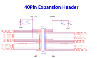
    This is a screenshot of the SCH (schematics) file from https://www.ti.com/lit/zip/sprr438, but the 40 pin expansion header has SPI5 pinned out it seems:

    Could you modify the device tree to use SPI5 instead of SPI6?

    Regards,

    Takuma

  • Hi,

    I couldn't find pad mapping for all 4 SPI pins and also this is used in u-boot dtsi

    CLK: J721E_IOPAD(0x1a0, PIN_INPUT_PULLDOWN, 12) /* (W29) RGMII6_TXC.MCASP10_AXR6 */
    CS0: J721E_IOPAD(0x19c, PIN_INPUT_PULLDOWN, 12) /* (W27) RGMII6_TD0.MCASP10_AXR5 */
    DO: J721E_IOPAD(0x198, PIN_INPUT_PULLDOWN, 12) /* (V25) RGMII6_TD1.MCASP10_AXR4 */
    DI: W24 - we couldn't find

    Could you please help me on this?

    Thank you,

    Neeraj

  • Hi Neeraj,

    this is used in u-boot dtsi

    CLK: J721E_IOPAD(0x1a0, PIN_INPUT_PULLDOWN, 12) /* (W29) RGMII6_TXC.MCASP10_AXR6 */
    CS0: J721E_IOPAD(0x19c, PIN_INPUT_PULLDOWN, 12) /* (W27) RGMII6_TD0.MCASP10_AXR5 */
    DO: J721E_IOPAD(0x198, PIN_INPUT_PULLDOWN, 12) /* (V25) RGMII6_TD1.MCASP10_AXR4 */

    That is a bit strange. Through device tree overlay files, the 40-pin header of SK-TDA4VM can be configured like the diagram in the following documentation: https://software-dl.ti.com/jacinto7/esd/processor-sdk-linux-edgeai/TDA4VM/08_06_01/exports/docs/devices/TDA4VM/linux/pi_hdr_programming.html

    If these pins are hogged and pinmuxed for MCASP, then GPIO should not work, or at least, overlaying as GPIO should make something not work due to resource conflicts. Is this in the dtsi file for the SK board, or are you using a custom board?

    Otherwise, for "DI: W24 - we couldn't find", the sysconfig tool would be a good place to start: https://www.ti.com/tool/SYSCONFIG. If you launch it in a browser and select J721E_DRA829_TDA4VM_AM752x as the device, and add in a SPI peripheral, it should generate the pinmuxing for device tree. To note, this only does the pinmuxing, so the other portions of Keerthy's FAQ still need to be followed. But, the sysconfig tool should save the trouble of having to go through the datasheet to decipher the correct pinmux value and offset.

    Regards,

    Takuma

  • Hi Takuma,

    " Is this in the dtsi file for the SK board, or are you using a custom board?" not sure if I missed providing any info if you relook the query (SK-TDA4VM: How to enable SPIDEV into TDA4VM) I asked and shared info there.

    I referred sysconfig online tool and generated devicetree.dtsi to see pin numbers. but never got spi under /dev after multiple tries.

    Since this is the only change I want in device tree, could you please share the only changes what are needed considering I have SK-TDA4VM board and want to use SPI with CS0 in 40-pin header?

    Thank you,

    Neeraj

  • Hi Neeraj,

    not sure if I missed providing any info if you relook the query

    Apologies, just wanted to make sure about the pinmuxing, since it was alarming to me that these pins were being pinmuxed as McASP for the SK board. This should not be happening, so I wanted to confirm if there was a difference in setup between us - I have seen many cases where SK-TDA4VM is mixed up with J721EXSOMXEVM, and custom boards. In this case, it seems there has not been a mixup, since "40 pin header" is pretty unique to the SK-TDA4VM. But alarming/strange nonetheless to see McASP pinmuxed.

    Since this is the only change I want in device tree, could you please share the only changes what are needed considering I have SK-TDA4VM board and want to use SPI with CS0 in 40-pin header?

    Sure, I can try to create a dtbo files to apply on top of 8.6.1 for enabling SPI, or create a patch to the dts file to do the same. I apologize again, but please expect at least a couple of weeks (2~3 weeks) to go through this process due to bandwidth from myself and the team. In the meantime, if the new dts file changes can be shared, we can take a look at it and continue to share comments as we have been doing so for the past week.

    Regards,

    Takuma

  • Hi Neeraj,

    Attached are two files. One is a prebuilt dtb file that can be dropped into rootfs partition's boot folder which should work with default Edge AI SDK image's Linux kernel for SK-TDA4VM, and the other is a patch for generating the dtb.

    k3-j721e-sk.dtb

    0001-SK-TDA4VM-Processor-SDK-Linux-8.6.1.2-patch-for-SPI5.patch

    I have confirmed spidev comes up under /dev folder, enumerated as spidev8.0 (it should be using spi5 nonetheless). I have not been able to test with an actual SPI device on the other end to receive transmissions, but using spidev_test as mentioned in this appnote it seems like things are being transmitted: https://www.ti.com/lit/an/sprad26/sprad26.pdf

    Let me know if this works on your set up.

    Regards,

    Takuma